
Installation manual


Série 32 Mlift Vector - Prog.Vectorielle Installation manual Chapter I - page 21
POWER-UP FOR INITIAL MOVEMENT (4/4)
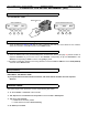
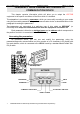
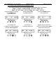
To check the capacitor voltage:
CUT THE SAFETY LANE!
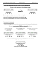
To check the VEC12 current measuring device:
• Check at addresses 12A and 12E that the value is between 500 and 524. If the values are not coherent,
check the connection of the K8 connector of the VEC01 board.
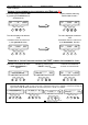
To check the incremental encoder connection:
•
Check at address 116 on the parameter/diagnostic communication device (see page 28) that the number of
impulses increases as you turn the rotor in the direction corresponding to up, and decreases in the
direction corresponding to down. Turn the rotor gently by hand.
If the number of impulses changes in the wrong direction, inverse the CAI and CBI wire on the KC22 (bottom)
connector of the VEC01 board.
Check that the parameters are coherent (see Chapter VII Frequency
drive parameters):
RECONNECT THE SAFETY LANE!
Try an up movement and then a down movement, and check that the lift starts off in the required
direction.
Possible faults:
The system might come up with one or more of the following fault codes:
•
17: Phase failure or inversion of the controller.
•
102: Gap between the advised and real speed of more than 15% in Slow Speed.
•
100: Motor over-intensity.
♦ Cross two of the motor phases.
♦ Check that the encoder is wired correctly.
•
62: O03 tape head fault.
104 Tcont 10V
SELECT ADDRESS 104
PRESS CONTACTOR
L
104 Tcont 600V
THE VOLTAGE READ IS ABOUT 600V
MODIF. CLEAR VALID.
1000 100 10 1
MODIF. CLEAR VALID.
1000 100 10 1