
Installation manual


Série 32 Mlift Vector - Prog.Vectorielle Installation manual Chapter I - page 19
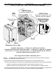
MINIMUM CONNECTIONS NECESSARY
FOR INITIAL MOVEMENT (2/4)
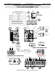
During the construction phase, you can temporarily use the 0V, GM and GD inputs on the
KM12 connector for running up and down respectively.
CONNECT AS FOLLOWS:
(See on page 18 for where to make these connections)
!
W
ARNING
: D
O NOT CONNECT THE
L1, L2, L3
POWER SUPPLY TO
11, 12, 13
OR YOU RISK DAMAGING THE TRANSISTORS
.
C
ONNECT POINTS
,
,
FOLLOWING THE ELECTROMAGNETIC
COMPATIBILITY RECOMMENDATIONS AS SHOWN ON PAGE
13.
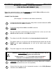
1
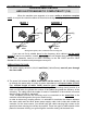
Connect the thermistor and/or the motor safety thermo-contact between the STH
and 0V terminals on the KM11 connector
2
Temporarily bridge 0V and INS on the KC23 connector.
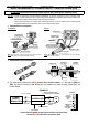
3
The "up" and "down" push buttons on the inspection box on the car roof to the
GM, GD and 0V terminals on the KM12 connector.
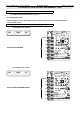
4
The safety circuits 1S, 6, 8 and 10 on the electromechanical terminal rail.
5
The traction motor to 11, 12 ,13 on the electromechanical terminal rail and the
EARTH to the earth collecting bar, as well as the brake power supply
+BR & -BR
6
The power supply to L1, L2, L3 and the Earth.
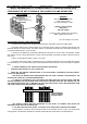
7
Temporarily bridge CS1 and 0V on KA13 and possibly CS2 and 0V on KA16 of
the BG19 board (when there are 2 door operators).
8
Connect the four wires on the incremental encoder to the KC22 (Bottom)
connector on the VEC01 board.