
Installation manual


Série 32 Mlift Vector - Prog.Vectorielle Installation manual Chapter VII - page 36
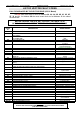
LIST OF VECTOR PARAMETERS AND FINAL VALUES
* You can visualise the parameters, inputs/outputs, variables as well as the function
graphs on a P.C., using the P313 interface board and the VISU P.C. programme.
To do this, connect the P313 set and push the 2 end buttons of the integrated diagnostic
tool VEC03. In order to make « READ PARAMETERS » appear on the display.
At the end on the P.C. visualisation, push the 2 end buttons.
AUTINOR
MODIF. CLEAR VALID.
1000 100 10 1
+
SOFTWARE
P313
VISUPC (LOCAL)
P.C.
VEC01
If the diagnostic tool is integrated in the VVVF,
it is ESSENTIAL to press the 2 end buttons.
READ PARAMETERS
You can visualise :
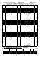
Address Name Designation
Min
Values
Max
Values
Factory Values
Finals
Values
Page
028
PileDef Fault 1
029
PileDef Fault 2
02A
PileDef Fault 3
02B
PileDef Fault 4
02C
PileDef Fault 5
02D
PileDef Fault 6
02E
PileDef Fault 7
02F
PileDef Fault 8
030
PileDef Fault 9
031
PileDef Fault 10
034
Dem Number of starts
(Full load)
0000 9999 0000xxxx 29
036
Dem Number of starts
(Empty)
0000 9999 xxxx0000 29
038
Visu1 *
VISU n° 1 Address
PROGRAMMATION F912
039
Visu2 *
VISU n° 2 Address
OF THE CURVES F910
03A
Visu3 *
VISU n° 3 Address
VISUALISED F904
03B
Visu4 *
VISU n° 4 Address
ON COMPUTER F908
040
HinTen Disable of voltage control 00
041
Test Transistor Test
(Program 55 for test)
00 29
042 Prog Programme Type VEC, SCA, ARB
29
043
TMan Controller Type Normal, 1 speed, 2 speed 29
044
Mcode Code no memory 0000 29
046
Code Code no entry 0000 29
• The theoretical graph : ................................................
F912
• The real graph :...........................................................
F910
• The capacitor voltage :................................................
F904
• The efficient motor current : ........................................
F908