
Installation manual


Série 32 Mlift Vector - Prog.Vectorielle Installation manual Chapter VII - page 32
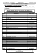
EXPLANATION OF OUTPUTS
• Address
101
:
Sor
, Outputs 0 to 7.
Segment
7
:
RISO
, Re-levelling Fault Relay.
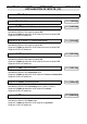
101 Sor
10000000
Indicates the State of the re-levelling fault relay output (
RISO on VEC06 board or controller
input
).
Segment 7 lights up when the re-levelling fault relay output is activated.
Segment 7 is not lit otherwise.
Segment
6
:
FR
, Brake relay.
101 Sor
01000000
Indicates the State of the Brake relay output (BR).
Segment 6 lights up when the brake relay output is activated.
Segment 6 is not lit otherwise.
Segment
5
:
DFP
, Fault Relay (Temporary).
101 Sor
00100000
Indicates the State of the Fault relay output (
DEF on VEC06 board or controller input
).
Segment 5 lights up when the fault relay output is activated.
Segment 5 is not lit otherwise.
Segment
4
:
DFI
, Fault Relay (Definitive).
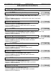
101 Sor
00010000
Indicates the State of the Fault relay output (
DEF on VEC06 board or controller input
).
Segment 4 lights up when the fault relay output is activated.
Segment 4 is not lit otherwise.
Segment
3
:
STOPR
, Stop VVVF.
101 Sor
00001000
Indicates the State of the Frequency Drive.
Segment 3 lights up when the Frequency drive is OFF.
Segment 4 is not lit otherwise.
Segment
2
:
VENT
, Fan relay.
101 Sor
00000100
Indicates the State of the Fan relay output. (VENT).
Segment 2 lights up when the fan relay output is activated.
Segment 2 is not lit otherwise.
Segment
1
:
S
, Safety relay.
101 Sor
00000010
Indicates the State of the Safety relay output (S).
Segment 1 lights up when the safety relay output is activated.
Segment 1 is not lit otherwise.
Segment
0
:
L
, Line relay.
101 Sor
00000001
Indicates the State of the Line relay output (L).
Segment 0 lights up when the line relay output is activated.
Segment 0 is not lit otherwise.