
Installation manual


Série 32 Mlift Vector - Prog.Vectorielle Installation manual Chapter VII - page 31
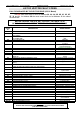
EXPLANATION OF INPUTS (2/2)
Segment
0
:
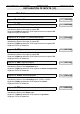
MO
, Up.
100 En1
00000001
Indicates the State of the Up input.
Segment 0 lights up when the lift is required to go up.
Segment 0 is not lit otherwise.
• Address
102
:
En2
, Inputs 0 to 7.
Segment
7
: NOT USED.
102 En2
10000000
Segment
6
: NOT USED.
102 En2
01000000
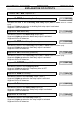
Segment
5
:
CCL
, L Contactor Check.
102 En2
00100000
Indicates the State of the Line Contactor.
Segment 5 lights up when the Line contactor is de-energised.
Segment 5 it is not lit when the Line contactor is energised.
Segment
4
:
CCS
, S Contactor Check.
102 En2
00010000
Indicates the State of the Safety Contactor.
Segment 4 lights up when the Safety contactor is de-energised.
Segment 4 it is not lit when the Safety contactor is energised.
Segment
3
: NOT USED.
102 En2
00001000
Segment
2
: NOT USED.
102 En2
00000100
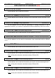
Segment
1
:
CAA
, Tape-head O03 - Beam A.
102 En2
00000010
Indicates the State of the Beam A (Top Beam) on the O03 tape-head.
Segment 1 lights up when the Beam A is cut.
Segment 1 is not lit otherwise.
Segment
0
:
CAB
, Tape-head O03 - Beam B.
102 En2
00000001
Indicates the State of the Beam B (Bottom Beam) on the O03 tape-head.
Segment 0 lights up when the Beam B is cut.
Segment 0 is not lit otherwise.