
Installation manual


Série 32 Mlift Vector - Prog.Vectorielle Installation manual Chapter I - page 15
ELECTROMAGNETIC COMPATIBILITY PRECAUTIONS (3/4)
CONCERNING THE SET OF WIRING IN THE LANDING COLUMN SEPARATION.
CONCERNING TRAILING CABLE SEPARATION.
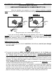
The devices controlled by the contactors are powered by wires which go into the trailing cable
The trailing cable's other conductor wires do not transport strong currents to activate power devices, but
electrical "DATA" via weak currents. This data could be, for example, the state of the door limits necessary to
control the automatic doors, or the car calls
.
To show you the difference in importance between the two types of current, here is an example: Certain
door motors can use 3 amps whereas the current used for the data concerning the state of the door limits is
only 3 mA
.
There is, in this typical example, a ratio of 1 to 1000.
This ratio is often even greater, especially when you consider the starting current of a power device when
it is first switched on. It is clear that the big currents will influence the little ones if care is not taken to separate
them
.
IF THESE CURRENTS IN THE TRAILING CABLE ARE NOT SEPARATED:
•
FALSE DATA WILL BE SENT TO THE CONTROLLER,
•
THERE WILL BE GRADUAL DETERIORATION OF THE ELECTRONIC COMPONENTS (ANYTHING FROM 3
DAYS TO A FEW MONTHS).
THE SHORT OR MEDIUM TERM CONSEQUENCES WILL BE SOME "STRANGE" FUNCTIONING BY THE
CONTROLLER, EVENTUALLY CAUSING BREAKDOWNS! ! !
TO SUM UP, IT IS ESSENTIAL THAT THE CONDUCTOR WIRES FROM THE TRAILING CABLE CARRYING
STRONG CURRENTS FOR THE RETIRING RAMP, DOOR MOTOR, BRAKING INJECTION, ANTI-CREEPS AND THE
CAR VENTILATION MOTOR, NOT TO MENTION THE CAR LIGHT AND SAFETY CHAIN, ARE SEPARATED FROM
THE OTHER CONDUCTORS CARRYING WEAK CURRENTS.
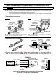
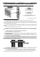
THE TRAILING CABLES MUST BE SEPARATED AS FAR APART AS POSSIBLE AND SHOULD BE
ARRANGED IN THE SHAFT AS SHOWN BELOW:
IF YOU ARE USING HALF-WAY BOXES, YOU SHOULD ALSO TAKE CARE TO SEPARATE THE WIRES.
The precautions carried out above should be taken in the controller as well. In fact, you should avoid
crossing wires in all directions behind the controller and should leave a little slack to aid maintenance
.
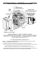
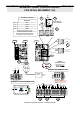
WARNING:
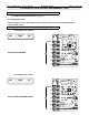
We recommend to separate
in the landing column,
the 3 sets of wiring in 3 rows:
Lighting - Power sockets
Safety lane
and Low Voltage,
in order for ease of maintenance and taking
EMC* regards into account
3 SET OF WIRING
LOW VOLTAGE (Low current)
SAFETY LANE (Safety current)
LIGHTING - POWER SOCKET (High current)
* EMC : ElectroMagnetic Compatibility
ONE OR SEVERAL
TRAILING CABLE
MECANICAL ATTACHMENTS
"WEAK CURRENT"