
Installation manual


Série 32 Mlift Vector - Prog.Vectorielle Installation manual Chapter VI - page 21
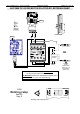
ELECTRONIC DOOR CONTROL UNIT OP15 1/2
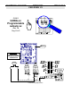
Presentation of the VVVF door card OP15.
The Electronic Door Control Unit OP15 has been designed to control 3 Phase AC
motor up to
0,3 kW
.
3 Phase Motor:
•
Programme Slow down contacts: ............
OP15
R
xx – xx/xx/xx
•
Programme Incremental Encoder: ...........
OP15
I
xx – xx/xx/xx
The VVVF door drive only independently runs the slow down contact, due to the
contact which are connected directly or to the incremental encoder.
The opening and closing command are given from the controller which receive
directly the end limit contacts or by the intermediately of the encoder which knows the
exact position of the leaves.
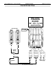
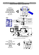
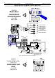
Connection diagram of Electronic Box.
The Open signal
should be connected to Terminal connector
K4
on
–
[2] and
+
[1]. (24V ~
or =)
The Close signal
should be connected to Terminal connector
K4
on
–
[4] and
+
[3].
(24V ~ or =)
The re-opening signal
should be connected to Terminal connector
K4
on
–
[6] and
+
[5].
(24V ~ or =)
The Fire Service signal
to do the Set-up speed on closing should be connected to
Terminal
K4
on
–
[8] and
+
[7]. (24V ~ or =).
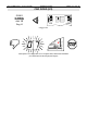
DO NOT CONNECT
WARNING !!!
ON THE MOTOR
A SUPPRESSOR
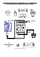
DOOR
SUPPLY
230 VAC
-
+
-
+
-
+
-
+
0V
16V
CA
CB
0V
CA
CB
0V
16V
CA
CB
AUTINOR
OP15
300W
OPENING SIGNAL
CLOSING SIGNAL
RE-OPENING SIGNAL
CLOSING NUDGING SIGNAL
SEE BELOW (*)
DIAGNOSTIC PLUG
SLOW DOWN LIMIT ON OPENING [OV-CB]
SLOW DOWN LIMIT ON CLOSING [OV-CA]
OU
INCREMENTAL ENCODER [OV-16V-CA-CB]
+
MOTOR
K3
1
2
3
4
1
2
3
4
5
6
7
8
1
2
3
4
FAULT SIGNAL
DEFAUT
FAULT
FEHLER
DIAG.
RISQUE DE CHOC ELECTRIQUE PENDANT
UNE MINUTE APRES MISE HORS TENSION
RISK OF ELECTRIC SHOCK DURING ONE
MINUTE WHEN THE ELECTRICITY SUPPLY
BEI FEHLENDER ABDECKUNG BLEIBEN DIE
TEILE EINE MINUTE NACH ABSCHALTUNG
EN L'ABSENCE DU COUVERCLE
HAS BEEN CUT, IN THE ABSENCE OF THE
DER STROMZUFUHR SPANNUNGSFÜHREND
COVER
K4
K5
SCREEN CABLE
(0,75 mm² [ref AUTINOR : 3444]