
Installation manual


Série 32 Mlift Vector - Prog.Vectorielle Installation manual Chapter VI - page 20
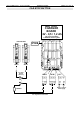
ELECTRONIC DOOR CONTROL UNIT OP06 OR OP11
Presentation of VVVF door card OP06 or OP11.
The Electronic Door Control Unit
OP06
or
OP11
has been designed to control 3
Phase AC motor or D.C. motor -
0,3 kW
(OP06) and
0,6 kW
(OP11).
3 Phase AC motor:
Programme
OP11 / OP06B - V07 14 MHz - 25/10/95
DC motor:
Programme
OP11 / OP06B - V07 CC - 10/02/95
The frequency drive regulates the doors' acceleration and deceleration, which can
be individually adjusted to suit the requirements of the application in both opening and
closing directions.
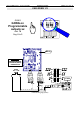
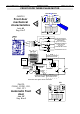
Connection Diagram of the Electronic Card.
OP06 or OP11
COM
OU
FC
OU
FC
FE
FE
COM
OV
+12
+16
CB
CA
J2
J1
J3
J4
PH3 PH1
PH2
J5
-+- +-+
DC
MOTOR
240 VAC
SUPPLY
TO S/EDGE
CIRCUIT
TERMINALS
CONNECTED IN DELTA
3 PHASE AC MOTOR 240V
NOTE : Position VVVF card as close
to door gear motor as possible
DO NOT CONNECT A P253 UNIT
TO THIS MOTOR
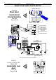
Open signal from the controller
, should be connected to Terminal connector
J4
on
PH2+
and
PH2-
.
Close signal
from the controller, should be connected to Terminal connector
J4
on
PH1+
and
J3
on
PH1-
.
Open Slow Down Limit
should be connected to Terminal connector
J2
on
0V
and
CA
.
Close Slow Down Limit
should be connected to Terminal connector
J2
on
0V
and
CB
.
Door Nudging
will be given from the controller and should be connected to Terminal connector
J3
on
PH3+
and
PH3-
. It is also required to give a door close signal.
Door re-opening is created due to an over-current which will energise the on-board relay. The relay
contact should be connected to the safety edge circuit to open the doors. The terminals to connect
to are marked
COM FC
and
FCFE
(normally open) of the
J1
connector.
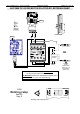
NOTE: The V.V.V.F. / Motor link should be as short as possible.
IMPERATIVE
Separate the conductors carrying large current and those carrying
electric information at low current.
For more information refer you at the documentation
[ref AUTINOR: 7276)