copertina vector marine 28-11-2006 17:42 Pagina 1 C M Y CM MY CY CMY K USE AND MAINTENANCE USO E MANUTENZIONE UTILISATION ET ENTRETIEN BETRIEB UND WARTUNG USO Y MANTENIMIENTO VECTOR MARINE ENGINES Publication edited by Marketing - Adv.
VECTOR SERIES We would like to thank you for buying an IVECO MOTORS product, and compliment you on your choice of engine. Before you carry out any operation involving the engine or its fittings, please read the contents of this manual carefully; compliance with the instructions provided in the manual is the best way to guarantee trouble-free, long term operation of the engine.
CONTENTS Page GENERAL INFORMATION . . . . . . . . . . . . . . . . . . . . . . . . . . . . . .3 Guarantee . . . . . . . . . . . . . . . . . . . . . . . . . . . . . . . . . . . . . . . . . . . . . .3 Spare Parts . . . . . . . . . . . . . . . . . . . . . . . . . . . . . . . . . . . . . . . . . . . . .3 Liability . . . . . . . . . . . . . . . . . . . . . . . . . . . . . . . . . . . . . . . . . . . . . . . . .3 Safety . . . . . . . . . . . . . . . . . . . . . . . . . . . . . . . . . . . . . . . .
GENERAL INFORMATION The following information is intended to encourage caution when using the engine, so as to avoid damage to persons or property as a result of improper or incorrect behaviour. The engines must only be used for the purposes indicated by the Manufacturer.
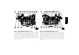
ENGINE TECHNICAL DATA V08 ENT The technical code and serial number are indicated on a plate, which is located on different parts of the engine, according to the model: flywheel casing, tappet cover, coolant tank.
ENGLISH 05_102_V 05_101_V Engine: VECTOR V08 ENT M75 / M12 Engine: VECTOR V08 ENT M75 / M12 1. Air filter clogging sensor - 2. Air filter - 3. After-cooler heat exchanger - 4. Exhaust gas discharge - 5. Lifting U-bolt - 6. Common Rail fuel distributor - 7. Thermostat valve location - 8. Lifting U-bolt - 9. Fuel filters switchover - 10. Fuel filters - 11.
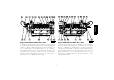
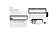
ENGINE TECHNICAL DATA V12 ENT The technical code and serial number are indicated on a plate, which is located on different parts of the engine, according to the model: flywheel casing, tappet cover, coolant tank.
ENGLISH 05_104_V 05_103_V Engine VECTOR V12 ENT M11 / M18 Engine VECTOR V12 ENT M11 / M18 1. Air filter - 2. Air filter clogging sensor - 3. After-cooler heat exchanger - 4. Exhaust gas discharge - 5. Lifting U-bolt - 6. Air intake deparator/ manifold - 7. Common Rail fuel distributor -8. Thermostat valve location - 9. Lifting U-bolt - 10. Fuel filters switchover - 11.
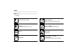
SIGNS Certain warning signs are affixed to the engine, and their meanings are indicated below. NOTE: The signs with an exclamation mark on them underline a potential danger. Lifting point (engine only). Danger of burning: Expulsion of hot water under pressure. Fuel Cap (on the fuel tank, if there is one). Danger of burning: Presence of high temperature parts. Oil Cap. Danger of fire: Fuel present. Danger of impact or catching on moving parts: Presence of fans, pulleys, belts or the like.
USE WARNING PRELIMINARY CHECKS For engines fitted with an electric pre-lubrication system Press the engine electric system power switch to start the pre-lubrication function, for which the relevant indicator light will turn on. Start-up of the engine, as described in the following pages, must only take place after allowing a sufficient amount of time to complete prelubrication, or after the indicator light has gone out.
STARTING AND STOPPING THE ENGINE FROM THE ANALOGUE CONTROL PANEL Procedure for start-up from the main IVECO MOTORS control panel 2 5 4 Make sure that the electrical switch indicating ENGINE ROOM BRIDGE on the Relay Box unit (located near the engine room) is in the BRIDGE position, then proceed as follows: 1. Lift the protective cover over the key switch (8), insert the key and turn it to the right to position 8B. 2.
WARNING 2 1 In order to ensure that the on-board control panels function properly during navigation, it is essential that the engine only be started after testing of the indicator lights and beeper has been completed. 3 1 Enable the secondary control panel, by turning the key switch on the main panel to position 8B (see requirements and procedure given in previous paragraph). 2.
Stopping the engine It is recommended that you run the engine for a few minutes at minimum speed and with no load before stopping it; this will allow the temperature to drop evenly and will avoid harmful thermal shocks. A. The engine is stopped from the main IVECO MOTORS control panel by turning the key switch to the rest position 8A. B. The IVECO MOTORS secondary control panel is stopped by pressing the red button (6) on the control panel.
RECOGNISING ALARMS IVECO MOTORS on-board control panels with analogue instruments are fitted with an electronic module that includes the indicator lights and the interface, timer and alarm storage circuits. The figure illustrates the dial and the key indicates the meaning of the alarm signals sent by all the indicator lights; some types of engine and relevant equipment only make some of the above mentioned functions available .
MANAGING THE ENGINE FROM THE RELAY BOX The box contains the components that protect the electrical lines from accidental short-circuits or excessive current absorption. These components do not require replacing, as the electrical continuity of the circuit will be restored automatically as soon as the malfunction ceases.
Indicator (Maintenance interval expired) The acceleration/deceleration function (RPM+ / RPM-) is only active when switch 1 is in the "ENGINE ROOM" position and switch 2 is in the “IGNITION” position. Acceleration (RPM+) Press button 4 in position RPM +, for a progressive increase in engine speed; this increase stops when the button is released, and the speed reached will be maintained until the next operation is carried out.
FOR PROPER USE OF THE ENGINE SPECIAL WARNINGS Coolant temperature high Do not continue to press the starter, when the engine has started. Do not remain in dock while waiting for the engine to warm up, but after starting, commence navigation at low speed; the working temperature will be reached properly with the engine running at medium speeds. Do not operate the engine at minimum speed for long periods, as this encourages the production of harmful exhaust and does not guarantee optimum performance.
Water in the fuel pre-filter Battery recharge or alternator malfunction It is a good rule to drain the water from the filters, before the relevant indicator comes on. Avoid using the engine with the fuel tank only a small reserve of fuel; this encourages the formation of condensation and makes it more likely you will suck up dirt or air, resulting in engine stoppage. Check it or have it checked periodically for cleanliness, wear and proper tensioning of the drive belt.
REFUELLING Parts to be supplied Cooling circuit (1) Lubrication circuit (2) total capacity (3) Periodic changing: oil sump at minimum level oil sump at maximum level Fuel tank (4) (4)Only use normal commercial diesel fuel (EN 590 standards). Do not use additives. Do not use fuels derived from the synthesis of organic substances and vegetable oils (Biodiesel). V08 ENT litres (kg) V12 ENT litres (kg) 70 110* WARNING 50 (45.5) 72* (65) 20 (18.2) 40 (36.
• replacing or topping up lubricant (hot engine oil may cause burns and scalds. Only carry out these operations when the oil has dropped to a temperature of below 50°C). When working in the engine compartment, pay particular attention to how you move, to avoid contact with moving parts or high temperature components. Wear goggles and use high pressure air jets (maximum air pressure used to clean is 200 kPa (2 bar, 30 psi, 2 kg/cm2).
Planned or Level 1 maintenance Frequency CAUTION! Do not carry out maintenance operations when the electric power supply is turned on: always check to ensure that the appliances are properly earthed. During diagnosis and maintenance operations, make sure that your hands and feet are dry, and whenever possible use insulating stands.
Frequency Change electrical injectors 3000 hours Change coolant pump 3000 hours Change sea water pump 3000 hours Adjust play in valves-rocker arms 3000 hours Clean the turbocharger 3000 hours (5) Clean heat exchangers 6) Given the nature of the heat exchangers used, cleaning must only be carried out by IVECO MOTORS Technical Service Network staff. 7) Must be performed annually, even if the required number of working hours are not reached.
REQUIREMENTS HOW TO PROCEED Checking oil level in engine Do not disconnect the batteries with the engine running. Do not carry out arc welding operations in the vicinity of the engine without first removing electrical cables and electronic units. After each maintenance operation involving disconnection of the batteries, make sure that the terminals have been properly locked onto the poles. Do not use battery chargers to start the engine. Disconnect the on-board network batteries when recharging.
Checking exhaust pipe/s for damage 2 1 Visually check that the exhaust system is not blocked or damaged. Make sure that there is no risk of dangerous fumes within the vessel. Contact the Boatyard if necessary. The high risk of refuelling with fuel that is polluted by foreign bodies and water means that it is necessary to perform this control even if no alarm is shown on the on-board control panel. Proceed with the engine stopped. Place a container under the pre-filter to collect the fluid.
Checking the level of electrolyte solution in the batteries CAUTION! Place the batteries on a level surface, then proceed as follows. Visually check that the fluid level is between the "Min" and "Max" limits; in the absence of references, check that the fluid covers the Lead plates inside the elements by approximately 5 mm. If necessary, top up with distilled water only those elements in which the level is below minimum.
1 05_020_V 05_008_V Checking corrosion of zinc anodes Only proceed with the engine stopped and at a low temperature: Provide suitable containers to ensure that no water is dispersed inside the vessel during removal of the anodes. Remove the anodes (1), unscrewing them from their housings (see location in the section ENGINE TECHNICAL DATA). Make sure that corrosion has not exceeded 50% of the volume of zinc. If this is the case, change them.
Using the dipstick (1), check that the oil level is between the "Min" and "Max" levels. Close the drainage tap (4). Dispose of used oil according to current requirements. Open the tap (4) and press and hold button A on the electronic module in the DISCHARGE position, until the sump has emptied completely. Changing oil filters A #(!2'% Only use filters with a filtration level equivalent to the ones you are replacing (or as indicated in the secion FREQUENCY).
Only use filters with a filtration level equivalent to the ones you are replacing (see section FREQUENCY). If you intend to proceed with the engine stopped Only proceed with the engine at a low temperature, so as to avoid the risk of burning. Remove the filters (2/3) by unscrewing them. Damp the new filter seal with gasoline or engine oil. Hand screw the new filters into place until the seal gasket touches the support, then lock by a further 3/4 of a turn. Bleed any residual air as described below.
Stop the engine, remove the pipe and lock the manifold to the prescribed torque. Start the engine following the instructions described above. Bleeding air from the fuel circuit 1 2 3 Ensure that any fuel coming out of the manifolds is not dispersed into the environment. CAUTION! Do not attempt to bleed the system in any way, as this is unnecessary and extremely dangerous. 05_016_V 1. Bleeder pipe on prefilter - 2. Bleeder pipe on filter support 3. Bleeder pipe on high pressure pump.
Checking tension or changing alternator belt 4 1 1 2 1 ENGLISH Fit the water sensor on the new filter, making sure that the threads are compatible. Loosen the bleeder manifold (2) and activate the hand pump (1) on the pre-filter support until the supply circuit is full. Start the engine and run it at minimum speed for a few minutes to eliminate any residual air.
1 3 2 1 2 05_122_V 05_021_V Insert the new filter and relevant gasket, taking care that it is fitted the right way round, i.e. with the metal reinforcements (3) facing outwards. Replace the cover and the gasket on the filter housing. Bleed the circuit and top-up if necessary, as indicated in the section INDICATIONS FOR INITIAL START-UP. Changing oil vapour filter Only proceed with the engine stopped and at a low temperature, so as to avoid the risk of burning.
The operations necessary to embark and disembark the engine must only be carried out by technicians from Authorised Service Centres. When lifting the engine only, use the U-bolts indicated in this manual in the section ENGINE TECHNICAL DATA and marked on the engine with special stickers. Lifting must be carried out using a rocker arm that keeps the metal cables supporting the engine parallel, using all the U-bolts provided simultaneously; the use of a lower number of U-bolts is not allowed.
LONG PERIODS OF INACTIVITY 7. Drain the residual 30/M protective oil from the sump. This oil can be used again for a further 2 preparation operations. 8. Fit signs reading ENGINE WITHOUT OIL to the engine and to the on-board control panel. 9. Drain the coolant, if it has not been mixed with suitable antifreeze and corrosion inhibitors, and affix a sign to indicate the fact.
4. Remove the plugs and/or seals from the suction, delivery, ventilation and bleeder openings in the engine, restoring it to a normal state of use. Connect the turbocharger suction inlet to the air filter. 5. Connect the fuel circuits to the vessel’s fuel tank, completing the operations as indicated in point 4. of PREPARING THE ENGINE FOR A LONG PERIOD OF INACTIVITY.
ENGINE MALFUNCTIONS CHECK indicator Located on the relay box, this indicates the electronic injection control malfunction codes (7 figure on page 14). The codes are emitted every time a malfunction is recognised, and is repeated continuously until the cause of the problem is dealt with; the sequence of different malfunction codes is known as a "list" and the list of codes is repeated continuously in the same order; a 6 second pause separates each repeat of the lists.
If the preset thresholds are exceeded a malfunction is detected, and this is signalled by light-up of the indicator (9 figure on page 14). Two different light-up modes indicate respectively: Flashing - Normal limit exceeded by a limited amount; the helmsman will not notice any difference in the way the engine runs.
EMERGENCIES ON BOARD 2. Do not attempt to remove pieces of clothing that may have stuck to the skin. 3. In the case of scalding, immediately but carefully remove any clothing that may be soaked in the hot liquid. 4. Cover the burn with a special burn dressing or sterile bandage. The user of a vessel that has been constructed according to safety regulations, when following the instructions provided in this manual and the indications given on the engine labels, will be working in safe conditions.
Injuries and fractures ENGLISH The vast number of possible circumstances and the specific nature of operations required means that the intervention of a medical team is necessary. 1. In the event of bleeding, keep the edges of the wound pressed together until help arrives. 2. If there is any suspicion of a fracture, do not move the injured part and only move the patient if absolutely necessary. Caustic burns Caustic skin burns are caused by contact with extremely acid or alkaline substances.
& 6$( : 6$( : 6$( 6$( 6$( : 6$( : 6$( : 6$( : PLQHUDO EDVH 6$( : VHPLV\QWKHWLF EDVH 6$( : VHPLV\QWKHWLF EDVH 6$( : V\QWKHWLF EDVH 6$( : V\QWKHWLF EDVH 38 )
CONTROL PANEL OPERATING REQUIREMENTS The following information refers to IVECO MOTORS equipment in its original configuration. The requirements and technical characteristics of customised equipment may differ from those set out here, and specific information must be provided by those responsible for preparing it. IVECO MOTORS on-board control panels With analogue instruments With digital instruments from -10°C to +60°C from -10°C to +60°C min. -20°C / max. +75°C min. -20°C / max.