
Operating instructions
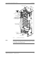

Vector Control Chassis Type Frequency Converter Connecting-up
SIEMENS AG 476 869 4070 76 J AB-74
SIMOVERT MASTERDRIVES Operating Instructions 7-7
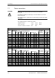
7.2 Auxiliary power supply, main contactor or bypass
contactor
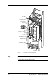
The 5-pole terminal strip is used for connecting up a 24 V voltage
supply and a main or bypass contactor.
The voltage supply is required if the inverter is connected up via a main
or bypass contactor.
The connections for the contactor control are floating.
The position of the terminal strip can be seen from the connection
overviews.
Terminal Designation Description Range
5 Main contactor control Main contactor control AC 230 V
4 Main contactor control Main contactor control 1 kVA
3 n.c. Not connected
2 0 V Reference potential 0 V
1 +24 V (in) 24 V voltage supply DC24 V ≤ 3.5 A
Connectable cross-section: 2.5 mm² (AWG 12)
Table 7-3 Connection of external DC 24 V aux. voltage supply and main contactor
control (types E, F, G)
The excitation coil of the main contactor has to be damped with
overvoltage limiters, e.g. RC element.
The 5-pole terminal strip is used for connecting up a 24 V voltage
supply and a main or bypass contactor.
The connection base is easily accessibly located on the DIN rail below
the slide-in unit of the electronics box.
The voltage supply is required if the inverter is connected up via a main
or bypass contactor.
The connections for the contactor control are floating.
Terminal Designation Description Range
5 Main contactor control Main contactor control AC 230 V
4 Main contactor control Main contactor control 1 kVA
3 n.c. Not connected
2 0 V Reference potential 0 V
1 +24 V (in) 24 V voltage supply DC24 V ≤ 4.3 A
Connectable cross-section: 2.5 mm² (AWG 12)
Table 7-4 Connection of external DC 24 V aux. voltage supply and main contactor
control (Type K)
The excitation coil of the main contactor has to be damped with
overvoltage limiters, e.g. RC element.
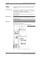
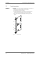
Types E, F, G:
X9 - external DC 24
V supply, main
contactor control
5
4
3
2
1
NOTE
Type K:
X9 - external DC 24
V supply, main
contactor control
5
4
3
2
1
NOTE