
Operating instructions


Maintenance Vector Control Chassis Type Frequency Converter
476 869 4070 76 J AB-74 Siemens AG
12-14 Operating Instructions SIMOVERT MASTERDRIVES
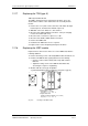
12.21 Replacing the pre-charging resistors (R1 - R4, type K)
These are situated on the right next to the TDB board in the rectifier
section.
♦
Remove the cover (undo screws, then detach first the right-hand
snap catch and then the left-hand snap catch).
♦
Disconnect the PUD and the NUD connections of the pre-charging
resistors R1 - R4 (M4, Torx).
♦
Detach the pre-charging resistors and take them out.
♦
Install the new pre-charging resistor with torque of 20 Nm ± 10 %.
Do NOT tilt the pre-charging resistor!
♦
Mount the fastenings and the connections in the reverse sequence.
See figure under section "Replacing the thyristor modules"
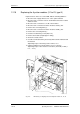
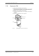
12.22 Replacing the circuit resistor
♦
Take out the capacitor battery.
♦
Take out the SML and SMU modules.
♦
Remove the module busbars.
♦
Undo the fixing screws (2 x M5, torque: max. 1.8 Nm) and take out
the circuit resistor.
♦
The new resistor must be thinly and uniformly rolled in a thermo-
lubricant.
♦
Max. torque of the electrical connections: 1.8 Nm.
♦
Install the new circuit in the reverse sequence.
CAUTION
Construction type K