
Operating instructions


Maintenance Vector Control Chassis Type Frequency Converter
476 869 4070 76 J AB-74 Siemens AG
12-12 Operating Instructions SIMOVERT MASTERDRIVES
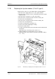
12.19 Replacing the thyristor modules (V1 to V3, type K)
Replacement as in the case of the TDB, with the following additions:
♦
Disconnect the supply cables C+ D
−
of the option terminals
♦
Disconnect the connection of the C and D bars between the rectifier
and the inverter.
♦
Disconnect the connections U, V, W of the modules.
♦
Disconnect the connections between modules and C(+) bar.
♦
Remove the connecting bar C(+).
♦
Disconnect the connections between modules and D(
−
) bar.
♦
Remove the connecting bar D(
−
).
♦
Undo the module fixing screws (M6, Torx).
♦
Remove the module (weight approx. 500 g).
♦
Clean the contact surface.
♦
Coat the new modules thinly and evenly with a thermo-lubricant and
mount them.
Tightening torque of the fixing screws: 6 Nm ± 15 %.
♦
Further installation is performed in the reverse sequence.
Tightening torque of the electrical connections (C and D): 12 Nm (+
5 %,
−
10 %).
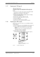
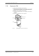
Fig. 12-6 TDB board, pre-charging resistors and thyristor modules V1, V2, V3