
Operating instructions

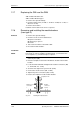

Maintenance Vector Control Chassis Type Frequency Converter
476 869 4070 76 J AB-74 Siemens AG
12-10 Operating Instructions SIMOVERT MASTERDRIVES
♦
Remove the VDU and the VDU resistor (if present).
♦
Remove the VDU retainer plate.
♦
Detach the plug-in connections on the PSU.
♦
Undo the screws (six Torx M4 screws) on the PSU.
♦
Take out the PSU.
♦
Install the new PSU in the reverse sequence.
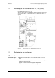
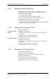
12.16 Replacing the IGD
IGD: IGBT Gate Drive
♦
The IGD board is mounted directly on the IGBT modules.
♦
Take out the capacitor battery.
♦
Remove the electronics box with IVI board for type E.
♦
Mark the output wiring U2/T1, V2/T2 and W2/T3 and disconnect it.
♦
Remove the inverter bus module after unscrewing the twelve M6
screws.
♦
Withdraw connector X295.
♦
Undo the fixing screws and remove the IGD board.
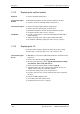
♦
The IGD board is mounted directly on the IGBT modules.
♦
Take out the capacitor battery.
♦
Remove the SML and SMU modules.
♦
Remove the module busbars.
♦
Remove the fiber-optic cables or connector X295.
♦
Withdraw connectors X290 and X291.
♦
Undo the fixing screws and remove the IGD board.
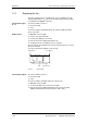
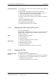
The spacing between the plus busbar and the minus busbar must be at
least 4 mm. In order to install the module busbars, you must therefore
use a template, e.g. a 4 mm thick piece of plastic.
♦
The IGD board is situated behind the module busbars.
♦
Take out the capacitor battery.
♦
Take out the SML and SMU modules.
♦
Remove the module busbars.
♦
Remove the nine fiber-optic cables at the top of the IGD.
♦
Withdraw the P15 feeder cable.
♦
Undo the fixing screws and remove the IGD board.
♦ Install the new IGD in the reverse sequence.
Make sure when doing so that you push in the fiber-optic cables up
to the endstop.
Construction type K
Construction types
E and F
Construction type G
NOTE
Construction type K