
Operating instructions


Vector Control Chassis Type Frequency Converter Maintenance
SIEMENS AG 476 869 4070 76 J AB-74
SIMOVERT MASTERDRIVES Operating Instructions 12-7
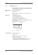
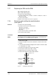
12.9 Replacing the balancing resistor
The balancing resistor is situated in the rear installation level on the
heat sink between the inverter modules, i.e. behind the capacitor
battery and the module busbars.
♦
Remove the capacitor battery.
♦
Remove the module busbars and the IGD module.
♦
Undo the fixing screws and take out the balancing resistor.
♦
Install the new component in reverse sequence.
♦
The balancing resistor is tightened with 1.8 Nm.
Coat the base plate evenly and thinly with a thermo-lubricant, paying
attention to correct contact assignment.
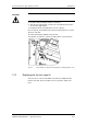
12.10 Replacing the PCU (types E to G)
PCU: Pre-Charge Unit
♦
Withdraw connector X39.
♦
Remove the screws at the bus connection U1/L1, V1/L2, W1/L3, C,
D and PE1.
♦
Unlock the spacers and take out the PCU.
♦
Install the new PCU in the reverse sequence.
♦
Take out the PCC unit.
♦
Withdraw connector X39.
♦
Remove the screws at the bus connection U1/L1, V1/L2, W1/L3, C,
D and PE1.
♦
Unlock the spacers and take out the PCU.
♦
Install the new PCU in the reverse sequence.
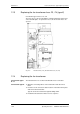
12.11 Replacing the PCC (types E to G)
PCC: Precharge Control Circuit
♦
Take out the PCU (type E and F).
♦
Withdraw connector X11, X12, X13 and X246 on the PCC.
♦
Disconnect the NUD cable.
♦
Remove the fixing screws of the PCC unit.
♦
Unlock the spacers and take out the PCC.
♦ Install the new PCC in the reverse sequence.
Construction types
E and F
Construction type G