
Operating instructions


Faults and Alarms Vector Control Chassis Type Frequency Converter
476 869 4070 76 J AB-74 Siemens AG
11-14 Operating Instructions SIMOVERT MASTERDRIVES
Fault
number
Fault Counter-measure
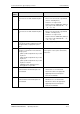
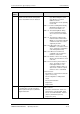
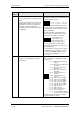
F103 Ground fault
There is a ground fault or a fault in the power
section.
During the ground fault test, a current flows
from the phase in which a valve has been
triggered, the overcurrent comparator has
responded, or a UCE monitoring has
responded in a phase in which a valve has
been triggered.
Read out fault value from r949. The digit of
the xth position indicates the valve where the
fault occurred at power-up.
x = 1 = V+ x = 2 = V- x = 3 =U+
x = 4 = U- x = 5 = W+ x = 6 =W-
Check the motor including the feeder cable
for short-circuit. If no ground fault is present,
check the power section for defective valves
(always conductive).
The digit of the xth position indicates the
phase in which I
≠ 0 and therefore a valve
must be defective (always conductive).
1 = Current in phase 1 (U)
2 = UCE in phase 2 (V)
1)
3 = Current in phase 3 (W)
4 = Only overcurrent occurred
The speed of the motor shaft during the
ground fault test should be less than 10 % of
the nominal speed!
1) A ground fault or a defective valve (aways
conductive) is present in phase V or the
switch for ‘SAFE OFF’ (X9/5-6) is open
(only for units with Order No. ...-11, ...-
21,...-31).
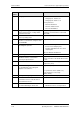
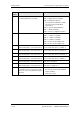
F107 MId I = 0
A fault has occurred during the test pulse
measurement.
Read out fault value from r949. The figures of
the grey shaded areas indicate which fault
has occurred.
xx = 01: Both current actual values
remain 0
xx = 02:
Motor-converter cable phase U
interrupted
xx = 03: Motor-converter phase V
interrupted
xx = 04: Motor-converter phase W
interrupted
xx = 05: Current actual value I1
remains 0
xx = 06: Current actual value I3
remains 0
xx = 07: Valve U+ does not trigger
xx = 08: Valve U- does not trigger
xx = 09: Valve V+ does not trigger
xx = 10: Valve V- does not trigger
xx = 11: Valve W+ does not trigger
xx = 12: Valve W- does not trigger
xx = 13: Sign I1 incorrect
xx = 14: Sign I3 incorrect
xx = 15: Sign I1 and I3 incorrect
xx = 16: I1 confused with I3
xx = 17: I1 confused with I3 and both
currents have an incorrect sign
The digit of the grey shaded area indicates
where the fault has occurred.