
Operating instructions


Vector Control Chassis Type Frequency Converter Faults and Alarms
SIEMENS AG 476 869 4070 76 J AB-74
SIMOVERT MASTERDRIVES Operating Instructions 11-13
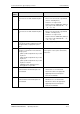
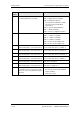
Fault
number
Fault Counter-measure
F098 MId Tachof
The rotating measurement has detected a
fault in the speed actual value signal. The
fault value defines the type of fault.
The fault message may have been
erroneously generated if the drive speed is
externally forced (e.g. completely locked drive
generates the "no signal" message)
The fault value in r949 defines the type of
intervention
4 No speed signal present
5 Sign of the signal is incorrect
6 A track signal is missing
7 Incorrect gain
8 Incorrect pulse number
Checking the measurement cables.
Checking the parameters
• P130 Src Speed ActV
• P151 Encoder Pulse #
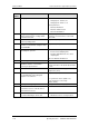
F100 GRND Init
During the ground fault test, a current not
equal to zero has been measured, or an UCE
or overcurrent monitoring has responded,
although no valve has yet been triggered.
The cause of the fault can be read out from
r376 "GrdFltTestResult".
Check the converter output for short-circuit or
ground fault
(-X2:U2, V2, W2 – including motor).
Check that the CU is inserted correctly.
Sizes 1 and 2:
• Check the transistor modules on the PEU
board -A23 for short-circuit.
Size 3 and 4:
• Check the transistor modules -A100,
-A200, -A300 for short-circuit
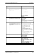
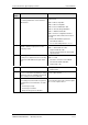
F101 GRND UCE
During the ground fault test, the UCE
monitoring has responded in a phase in
which no valve has been triggered.
Check valves in the power section for short-
circuit, and on converters with fiber-optic
gating, check the gating unit wiring and the
UCE checkbacks for correct assignment.
r376 can be interrogated to indicate which
UCE monitoring has responded.
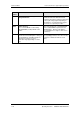
F102 GRND Phase
During the ground fault test, a current flows in
a phase in which no valve has been triggered
or the UCE monitoring has responded in the
phase in which the valve has been triggered.
The fault value can be read out from r949.
The digit of the xth position indicates the
valve where the fault occurred at power-up
x = 1 = V+ x = 2 = V- x = 3 =U+
x = 4 = U- x = 5 = W+ x = 6 =W-
The figure of the xth digit indicates the phase
in which I
≠ 0 and thus a valve must be
defective (always conductive).
x = 1 = Phase 1 (U)
x = 3 = Phase 3 (W)
x = 4 = Phase 1 (U) or 3 (W)
Examine phase for defective valves (always
conductive).