
User's Manual
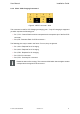
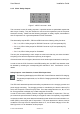
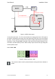
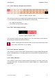
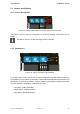
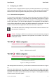
Table Of Contents

User Manual Installation Guide
2.4 Use Cases: vSECC in Different Scenarios
This section details the electrical connections required for the most common use cases.
Note that additional configuration may be required, e.g., setting the correct backend URI.
Please use the Web-UI or an already connected CSMS to configure the vSECC (see Section
3.1). The use cases could be combined easily.
2.4.1 Use Case 1: vSECC Stand-alone Operation, CCS Charging Ready
The goal is to be able to start up the vSECC.
1. Mount the vSECC such that no cable is bent and electrical short-circuits are
impossible.
2. Connect the X303 charging connector according to the pin descriptions de-
picted in Section 2.2.4. This plug relates to the first charging port.
3. Connect the X302 charging connector according to the pin descriptions de-
picted in Section 2.2.3. This plug relates to the second charging port.
4. Connect the ETH1 ethernet port to an ethernet network providing DHCP. This
allows the configuration of the vSECC via the Web-UI.
5. Connect the X307 power supply connnector. Take care of the correct polarity.
Ensure that 24 V and at least 200 mA are provided.
The vSECC starts up as soon as the power supply is connected. The System LED (see
Section 4.3) blinks green as long as the startup is running. After the vSECC has finished
initialization, the System LED turns green constantly.
The vSECC is now ready to be configured, e.g. for charging simulation purposes.
© Vector Informatik GmbH Version 1.2.0 27