
User's Manual
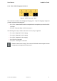
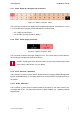
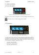
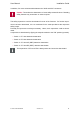
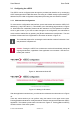
Table Of Contents

User Manual Installation Guide
2.3 Buttons and Switches
2.3.1 Factory Reset Button
Figure 12: vSECC reset button in the lower right corner (top view)
This button is used to reset the configuration to the factory defaults. See Section 4.1 for
details.
The vSECC version 1.2 does not support this functionality.
2.3.2 DIP Switches
Figure 13: vSECC connector: DIP Switches
In the lower right corner, right above connextor X305 and X307, DIP switches allow the
configuration of some vSECC functionality. The three blue switches allow the activation and
deactivation of terminating resistors. All three enable the termination if switched to the left
(on) and disable the termination if switched to the right.
> Left switch: CAN1 termination
> Middle switch: CAN2 termination
> Right switch: RS485 termination
© Vector Informatik GmbH Version 1.2.0 25