
User's Manual
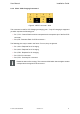
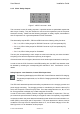
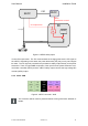
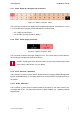
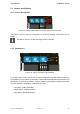
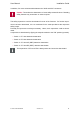
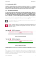
Table Of Contents

User Manual Installation Guide
2.2.7 X306 - Digital In and Digital Out Connectors
Figure 10: vSECC connector: X306
This connector is used for both digital input and digital output signals. See section 3.7.2 and
3.7.1 for details and a mapping of PEP-identifiers to connector pins.
> Pin 1 (REL1b) outputs 24V.
> Pin 26 (REL1a) is the ground pin (GND).
2.2.8 X307 - Power Supply Connector
Figure 11: vSECC connector: X307
This connector is used for the supply voltage of 24 V. The current drawn is below 200 mA,
so providing at least 200 mA should be sufficient.
Caution: Pressing the button above the X307 connector may cause a factory reset
of the vSECC. See Section 2.3.1 for details.
2.2.9 ETH1 - Ethernet 1 (Backend)
This connector is used to connect network entities such as a Charging Station Management
System (CSMS/Backend) or the Power Electronics Communication Controller (PECC) to
the vSECC.
2.2.10 ETH2 - Ethernet 2
This connector is used connect network entities to the vSECC in the same manner as it
is possible with ETH1. The second port allows a higher flexibility, e.g., regarding network
segmentation.
© Vector Informatik GmbH Version 1.2.0 24