
User's Manual
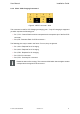
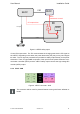
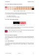
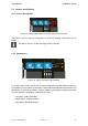
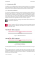
Table Of Contents

User Manual Installation Guide
2.2.5 X304 - Safety Outputs
Figure 7: vSECC connector: X304
This connector is used for safety purposes. It provides access to specialized outputs that
add a layer of safety. They are intended to connect to the respective inputs of the power
electronics circuitry. Please see the following paragraph on safety outputs, loss detection
and CP supervision for a general explanation of this mechanism.
The three safety outputs REL1, REL2 and REL3 serve the following safety functions:
> Pin 1 + 2, REL1: Safety output for IEC/SAE Connector 1 (CP and optionally PP)
> Pin 3 + 4, REL2: Safety output for IEC/SAE Connector 2 (CP and optionally PP)
and GB/T
> Pin 5 + 6, REL3: Safety output for CHAdeMO
The two pins corresponding to each output are wired such that they are short-circuited if
everything is fine and the respective output may be energized.
If the outlet must not be energized, the electric circuit remains open between the a and b pin.
In order to use the CCS Connector 2 with REL2 safety pins, the GB/T loss detection must
be disabled by switching the corresponding DIP switches to ”ON”. See Section 2.3.2 for
details.
Safety Outputs: Loss Detection, Control Pilot Supervision
The following details apply to the IEC 61851 Control Pilot line used for DC-charging.
The general principle holds, too, for IEC AC-Charging and the GB/T equivalent (AC
and DC).
The IEC 61851 standard imposes strict safety requirements on the charging process and
power supply monitoring. The charging process is controlled by the electric vehicle (EV)
which sets a specific Control Pilot (CP) state. Four state categories exist: Ax, Bx, Cx and
Dx. Energy transfer is allowed only in state categories Cx and Dx.
In order to enforce this, vSECC provides a logical output called CP supervision. This out-
put controls the power electronics’ ability to energize its outlet. Conceptually, a logical AND
conjunction exists in the power electronics between power electronics communication con-
troller (PECC) control input and CP supervision: The power electronics is able to close its
contactors if and only if the CP supervision allows it, i.e., the CP state category is Cx or Dx.
See Figure 2.2.5 for an illustration of this principle.
© Vector Informatik GmbH Version 1.2.0 22