
User's Manual
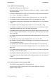
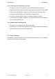
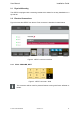
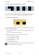
Table Of Contents

User Manual Installation Guide
2.2.2 X301 - Analog In and Temperature Sensor Connectors
Figure 4: vSECC connector: X301
This connector is used for both analog input signals and external temperature sensors. See
section 3.7.3 and 3.7.4 for details and a mapping of PEP-identifiers to connector pins.
2.2.3 X302 - CCS Charging Connector 2
Figure 5: vSECC connector: X302
This connector is used for CCS Charging at charging port 2. Only DC-charging is supported
yet which requires the following pins:
> Pin 7, CP2: Control Pilot line which corresponds to the respective pin of the second
CCS connector.
> Pin 8, PE: Protective Earth for CCS connector 2.
The following pins may be used in the future. For now, they are ignored:
> Pin 1, M2a: Required for AC-charging.
> Pin 2, M2b: Required for AC-charging.
> Pin 3, FB2: Required for AC-charging.
> Pin 5, PP2-PU: Not used.
> Pin 6, PP2: Proximity Pin. Not used.
Please be aware of the naming: The connector X302 which has the lower number
corresponds to the logical CCS connector 2.
© Vector Informatik GmbH Version 1.2.0 20