
User's Manual

User Manual VC-EVCC
© 2021 Vector Informatik GmbH Version 1.3.0 224
6.10 Real Time Clock
An unbuffered real time clock with timer and calendar functions. Alarm and timer functions
can additionally trigger a wake-up signal. The FBB ensures that the wake event can be read
by the µC after wake-up.
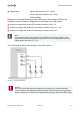
6.11 200mA High-Side Output
Caution
If the High Side Outputs of the VC-EVCC are used, measures must be taken to ensure
a load current greater than 15mA (HSOUT0, HSOUT1) respectively 330mA (HSOUT4).
An appropriate load resistor must be calculated depending on the supply voltage.
Otherwise, the VC-EVCC will detect an OpenLoad error which leads to a switch-off of
the High Side Output.
If in doubt, please contact the Vector support.
Digital Output for currents up to 200mA, used to drive small loads or as a status output for
other ECUs. The outputs have various optional configurations. Each of them can be used
as digital or analog inputs as a population variant.
Nominal voltage: 24V
Max. current: 200mA
Switching freq: static on-off / up to 400Hz
Diagnostics: Open Load (min. 15mA load required and V
Bat
≥ 10V )
Short to Ground
Short to Battery
6.12 Terminal 15 Signal Input
The VC-EVCC has a Terminal 15 input to wake-up the ECU.
Nominal voltage: 24V
Input signal range: 0V…36V
Low: ≤ 3.5V
High: ≥ 4.5V
Wake threshold: > V
Bat
– 2.5V
Filter: Lowpass (870Hz corner frequency)
6.13 Core
The Core FBB is defined by the microcontroller the external Watchdog and the supply of the
electronics.