
User's Manual


User Manual VC-EVCC
© 2021 Vector Informatik GmbH Version 1.3.0 219
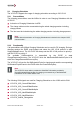
The following figure describes the recommended external wiring of CP and PE between the
inlet and the VC-EVCC via a 2-core-twisted-pair cable.
Figure 6-1 Recommended Wiring of CP and PE
6.2.3 LIN
A LIN communication with a data rate of 19.2 kbps between charging infrastructure and
vehicle via CP line according to SAE J3068 [9] is available.
6.3 Proximity Detection Logic (Plug Present)
A Functional Building Block to detect whether a charging cable is connected and to
determine the current load capacity of the connected cable. The FBB reads different resistor
values representing different currents the charging infrastructure is capable of and is also
capable to wake-up the hardware on communication. The implementation is according to
IEC 61851 [4] and SAE J1772 [10].
Meas. Range: 100Ω … 1500Ω based on a vehicle inlet resistor of 4700Ω
or 2700Ω
Pull up resistance: 330Ω
Filter: Lowpass (200Hz corner frequency)
Accuracy: According to IEC 61851 and SAE J1772
Diagnostics: Open Load
Short to Ground
Short to Battery
Out of Range
6.4 PT1000 Temperature Sensor Input
An analog input to connect PT1000 temperature sensors to it. A constant current source is
used to supply the temperature dependent sensor. The resulting voltage drop can be
measured at an ADC input of the µC.
Meas. Range: -50°C … +150°C (800Ω … 1,6kΩ)
Meas. Current: 1mA