
User's Manual


User Manual VC-EVCC
© 2021 Vector Informatik GmbH Version 1.3.0 218
6 Electrical Characteristics
This section describes the electronic design of the VC-EVCC.
Note
Options and variants described below shall give an overview of possible project
specific adaptions pre considered in the design.
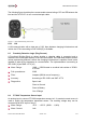
6.1 High-Speed CAN
High speed CAN Bus based on the TJA1043T transceiver which is fully ISO 11898-2:2003
and ISO 11898-5:2007 compliant. It is suitable for 24V applications and capable to wake-up
the hardware on bus traffic. A separate pin per CAN Signal is available for shielding of the
CAN lines if necessary.
Electric Strength: -58V … +58V
Caution
If a CAN channel is configured to work at 1Mbit/s the ECU cannot be woken up via that
CAN channel at temperatures below -30°C.
6.2 Control Pilot
Low- and high-level communication between charging infrastructure and vehicle is
performed via the CP line.
6.2.1 PLC
Powerline communication Functional Building Block based on the QCA7005 PHY suitable
for communication with vehicle charging infrastructure based on ISO 15118.
Interface to the host is a SPI with supported boot from host.
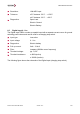
6.2.2 PWM
Low level PWM modulated communication between charging infrastructure and vehicle via
the CP line. It is based on a 1 kHz signal with an amplitude of ±12V according to IEC 61851
[4] and SAE J1772 [10].
Meas. Range: -15V…+15V
Sampling: 100 kHz
Diagnostics: Short to battery
The Control Pilot input is capable to wake-up the hardware on communication.
The vehicle can indicate readiness for charging with or without ventilation changing the
positive amplitude of the signal. The charging infrastructure can indicate the available
charging current by changing the duty cycle of the signal between 3% and 97%.