
User's Manual

User Manual VC-EVCC
© 2021 Vector Informatik GmbH Version 1.3.0 210
5.7 Charging Arbitration
The charging arbitration enables the operation of two VC-EVCCs on the same CAN channel.
It targets use cases which require two charging inlets per vehicle but only one charging inlet
is used for charging at a time.
5.7.1 Functionality
For charging arbitration, the VC-EVCC supports three selectable modes:
Passive node: The VC-EVCC has limited communication and functionality and has no
clearance to charge.
Active node: The VC-EVCC has normal communication and functionality but has no
clearance to charge.
Selected node: The VC-EVCC has normal communication and functionality and has a
clearance to charge.
If charging arbitration is not used the Charge Node Selection must be set to “off” (default
value). In this case the VC-EVCC uses the primary source address and operates always in
mode “Selected node”.
If charging arbitration is used the Charge Node Selection must be set to “on” via UDS. In
order to run two VC-EVCCs on the J1939 vehicle CAN, two different Source Addresses are
required. The configuration of both Source Addresses as well as the activation of the Charge
Node Selection via UDS is described in the chapter “UDS communication”. The VC-EVCC
selects the Source Address to be used for operation according to the input voltage of the
High Side Output 2 at startup. Please note that the High Side Output 2 is configured as an
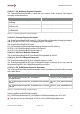
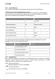
Input. The input voltage of the High Side Output 2 is interpreted as follows.
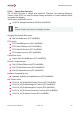
HS_OUT2 input voltage level
VC-EVCC Source Address
< 4500mV
Primary Source Address
>= 4500mV
Secondary Source Address
Table 5-69: HS_OUT2 Input Voltage Hysteresis
The VCU determines the VC-EVCC which is allowed to charge charge by setting the CAN-
signal VCVCCU_Vehicle_ChargeSelection to “PrimaryNode” or “SecondaryNode”. The
acknowledgement is sent by both VC-EVCCs within the signal
VCVCCU_Vehicle_ChargeSelectionAck.
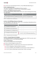
The mode of each VC-EVCC is determined as follows:
Passive node:
> VCVCCU_Vehicle_ChargeSelection is set to “PrimaryNode” and
> HS_OUT2 input voltage is pressed or
> VCVCCU_Vehicle_ChargeSelection is set to “SecondaryNode” and
> HS_OUT2 input voltage is not pressed