
User's Manual


User Manual VC-EVCC
© 2021 Vector Informatik GmbH Version 1.3.0 21
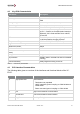
4.2 Key ECU Characteristics
Parameter
Description
CPU
SPC564B74L7, 120MHz
Memory
3,0 MB Code-Flash, 4x16 kB Data-Flash, 192 kB
RAM
Voltage range
8V … 32V (ISO 16750, Code E)
Overvoltage 2 min
48V
Connector
Molex CMC36 Hybrid Sealed (36 Pins)
Communication
3x CAN 2.0B (incl. shielding)
1x PLC – Power Line Communication based on
IEC61851, ISO 15118 and DIN 70121 with PP,
PE and CP
I/O
Extensive Inputs and Outputs typically needed for
in vehicle powerline charging systems
Temperature Range
-35°C … +85°C (ISO16750, Code H)
Typical Current Consumption without loads
150mA
Quiescent Current
203µA
Maximum Current Draw
12A
Recommended fuse (based on hardware
tests)
15A
Weight
560 g
IP protection
IP6K6K / IP6K7 / IP6K9K (not valid for unsealed
housing)
Functional Safety
Safety targets according to ASIL B
Table 4-1 VC-EVCC Key Characteristics
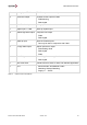
4.3 ECU Interface Characteristics
The following table gives an overview of the interfaces and functional blocks of the VC-
EVCC.
Count
FBB Name
Description / Configuration
3
High-speed CAN
CAN Interfaces
> Termination not populated
> 100nF capacitive ground coupling on CAN0 shield and
CAN2 shield
> Direct connected ground coupling on CAN1 shield
1
PLC
High Level Powerline Communication
1
Control Pilot
Low Level Powerline Communication
1
Plug Present
Proximity Pin logic