
User's Manual

User Manual VC-EVCC
© 2021 Vector Informatik GmbH Version 1.3.0 183
Signal
Description
Vehicle_LinkVoltage
The voltage at the vehicle side of the DC connection
Vehicle_ContactorVoltage
The voltage at the EVSE side of the DC connection
Vehicle_IsolationMeasurementRequest
The control request of the vehicle isolation
measurement
Vehicle_IsolationMeasurementStatus
The status of the vehicle isolation measurement
Vehicle_ContactorRequest
The Representation of the control request of the
vehicle contactors
Vehicle_ContactorStatus
The Representation of the status of the vehicle
contactors
ChargeV2G_PreChargeStabilityTime
The Representation of the time to wait during pre-
charge for the voltages being stable
ChargeV2G_MaxAllowedTemperature
The Representation of the maximum temperature of
the DC pins where V2G charging is still allowed:
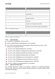
Table 5-48 Charging with V2G Signals
Parameter
Value
ChargeV2G_MaxAllowedTemperature
90°C
ChargeV2G_PreChargeStabilityTime
500ms
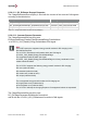
Table 5-49 Charging with V2G Parameters
5.5.8.1 Initial Situation
ControlPilot_ChargeMode is set to mode B.
Vehicle_IsolationMeasurementRequest is set to activated.
The VC-EVCC sets the following CAN signals initially and after any end of a V2G
sequence to the specified values:
VCVCCU_V2G_DateTimeNowFlag to 0 (FALSE)
VCVCCU_V2G_EVSECurrentRegulationToleranceFlag to 0 (FALSE)
VCVCCU_V2G_EVSEEnergyToBeDeliveredFlag to 0 (FALSE)
VCVCCU_V2G_EVSElsolationStatusFlag to 0 (FALSE)
VCVCCU_V2G_EVSEMaximumCurrentLimitFlag to 0 (FALSE)
VCVCCU_V2G_EVSEMaximumPowerLimitFlag to 0 (FALSE)
VCVCCU_V2G_EVSEMaximumVoltageLimitFlag to 0 (FALSE)
VCVCCU_Vehicle_ContactorRequest to 2 (ForceOpen)
5.5.8.2 Charge Error Detection
The VC-EVCC provides a charge error detection. Therefore, the following Diagnostic
Trouble Codes (DTC) are used to indicate missing information or invalid conditions which
are needed for charging.