
User's Manual

User Manual VC-EVCC
© 2021 Vector Informatik GmbH Version 1.3.0 180
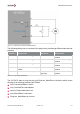
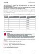
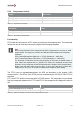
Figure 5-4: Characteristic Curve of PTC1 and PTC2 (PT1000)
The PTC1 and PTC2 can be activated/deactivated via UDS as described in the chapter
“UDS communication”. The DTCs of the PTC1 and PTC2 are only evaluated by the VC-
EVCC if the corresponding temperature sensor is activated.
All three temperature values of PTC0, PTC1 and PTC2 are set to error if the respective self-
diagnostic status is not OK.
5.5.7 Charging with Control Pilot
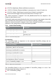
Signal
Description
Vehicle_ChargePermission
The permission from the vehicle to start
charging
ChargePwm_ModeBSettleTime
Time to pause the PWM charging after mode B
was entered
Table 5-46 Charging with Control Pilot Signals
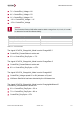
Parameter
Value
ChargePwm_ModeBSettleTime
1000ms
Table 5-47 Charging with Control Pilot Parameters
5.5.7.1 Functionality
The signal VCVCCU_ChargeUnit_State is set to mode C if
VCVCCU_Inlet_MotorStatus is Locked and
VCVCCU_PlugPresent_Status is Connected and
VCVCCU_ChargeUnit_Mode is ChargePwm and
VCVCCU_Vehicle_ChargePermission is set to Allowed and