
User's Manual

User Manual VC-EVCC
© 2021 Vector Informatik GmbH Version 1.3.0 179
5.5.6 Temperature Control
Signal
Description
PTC0_Temperature (AC temperature inlet pin)
The PTC0 temperature value
PTC1_Temperature (DC temperature inlet pin)
The PTC1 temperature value
PTC2_Temperature (DC temperature inlet pin)
The PTC2 temperature value
Table 5-43 Temperature Control Signals
Parameter
Value
PTC0_NormalTemperature
20°C
PTC0_CriticalTemperature
120°C
Table 5-44 Temperature Control Parameters
Functionality
PTC0 shall be connected to a PTC sensor according to the supported inlet. The measured
values are sent on CAN and used for the higher-level charging algorithm.
Note
Due to the specification of the supported inlet PTC0_Temperature is only sent on CAN
preprocessed. The signal only contains two different values related to the measured
resistance.
PTC0_NormalTemperature (600 Ohm <= PTC0_Resistance < 1500 Ohm)
PTC0_CriticalTemperature (1500 Ohm <= PTC0_Resistance <= 1600 Ohm)
The threshold of 1500 Ohm and the lower boundary of 600 Ohm are default values. If
other values are required due to a specific PTC sensor, the threshold and the lower
boundary can be configured via UDS as described in the chapter “UDS communication”.
Please note that both values must be within a range from 400 Ohm to 5000 Ohm.
Otherwise, the VC-EVCC is not able to measure the resistance value reliably.
The PTC0 can be activated/deactivated via UDS as described in the chapter “UDS
communication”. The DTCs of the PTC0 are only evaluated by the VC-EVCC if the PTC0 is
activated.
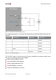
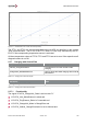
PTC1 and PTC2 shall be connected with a PT1000 sensor. The temperature is processed
from the measured resistance for PTC1 and PTC2 if the respective self-diagnostic status is
OK.
Parameter
Value
Critical temperature for DC Charging
90°C
Resistance of PTC1/PTC2
1347 Ohm
Table 5-45 Resistance Threshold of PTC1/PTC2 at the Critical Temperature of 90°C