
User's Manual

User Manual VC-EVCC
© 2021 Vector Informatik GmbH Version 1.3.0 177
7V < ControlPilot_Voltage < 8V
4V < ControlPilot_Voltage < 5V
1V < ControlPilot_Voltage < 2V
-11V < ControlPilot_Voltage < -1V
-13V > ControlPilot_Voltage
Caution
The Protective Earth to GND offset must be within a range from -2,1V to 2,1V in order
to detect the Control Pilot Status reliably.
VCVCCU_ChargeUnit_State
Control Pilot_PresentStatus
StateB2, StateC or StateD.
Active
StateA, StateB1 or StateE.
Not active
StateF or not available
Not available
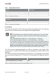
Table 5-40 Control Pilot Status
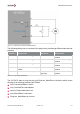
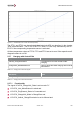
The signal VCVCCU_ChargeUnit_Mode is set to ChargeV2G if
ControlPilot_PresentStatus is active and
3% <= ControlPilot_DutyCycle <= 7%.
The signal VCVCCU_ChargeUnit_Mode is set to ChargePwm if
ControlPilot_PresentStatus is active and
8% <= ControlPilot_DutyCycle <= 97%.
The signal VCVCCU_ChargeUnit_Mode is set to ChargeLIN if
ControlPilot_Voltage equals 6V or 9V (tolerance ±1V) and
LIN frame SeInfoList has been detected by the LIN transceiver
The signal VCVCCU_ChargeUnit_Mode is set to ChargingNotAllowed if
ControlPilot_PresentStatus is active and
0% < ControlPilot_DutyCycle < 3% or
7% < ControlPilot_DutyCycle < 8% or
ControlPilot_DutyCycle > 97%