
User's Manual

User Manual VC-EVCC
© 2021 Vector Informatik GmbH Version 1.3.0 176
VCVCCU_DigitalInput_DebouncedStatus is pressed or
VCVCCU_S3Switch_DeboundedStatus is pressed (only in case of Combo1) or
VCVCCU_Vehicle_StopCharge is pressed (only if feature is activated) or
unlock movement trigger from an unsuccessful lock movement is set
The unlock movement is stopped if the Inlet_MaxMovementTime has elapsed or the
PlugLock_MotorStatus is error.
To prevent a locking movement directly after the unlock movement has stopped a timer (with
Inlet_UnlockedTime), during which no lock movement is allowed, is started.
When the unlock movement is stopped a timer (Inlet_OverloadTimeoutTime) for overload
protection is set, during which no motor movement is possible.
5.5.4 Control Pilot Handling
Signal
Description
VCVCCU_ChargeUnit_State
The state of control pilot signal
VCVCCU_ChargeUnit_Mode
The charge unit mode derived from the control pilot duty
cycle
VCVCCU_ChargeUnit_MaxCurrent
The maximum allowed current derived from the control
pilot duty cycle
Table 5-38 Control Pilot Handling Signals
Functionality
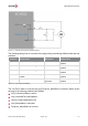
The ControlPilot_Status is dependent on the measured ControlPilot_Voltage and set
according to table A.3 in [4].
ControlPilot_Voltage
ControlPilot_Status
-1V <= ControlPilot_Voltage <= 1V and
PlugPresent_Status is not connected
StatusA
8V <= ControlPilot_Voltage <= 10V
and charge communication is not active
StatusB1
8V <= ControlPilot_Voltage <= 10V
and charge communication is active
StatusB2
5V <= ControlPilot_Voltage <= 7V
StatusC
2V <= ControlPilot_Voltage <= 4V
StatusD
-1V <= ControlPilot_Voltage <= 1V
and PlugPresent_Status is connected.
StatusE
-13V <= ControlPilot_Voltage <= -11V
StatusF
See below
Not available
Table 5-39 Setting of the Control Pilot Status
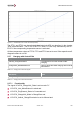
The ControlPilot_Status is set to not available if ControlPilot_Voltage is in one of the
following ranges (according to table A.3):
10V < ControlPilot_Voltage