
User's Manual

User Manual VC-EVCC
© 2021 Vector Informatik GmbH Version 1.3.0 171
Caution
If the High Side Outputs of the VC-EVCC are used, measures must be taken to ensure
a load current greater than 15mA (HSOUT0, HSOUT1) respectively 330mA (HSOUT4).
An appropriate load resistor must be calculated depending on the supply voltage.
Otherwise, the VC-EVCC will detect an OpenLoad error which leads to a switch-off of
the respective High Side Output.
If in doubt, please contact the Vector support.
In ON state a short to GND and an open load can be detected. A short to battery situation
will be detected as an open load.
In OFF state a short to GND, a short to battery and an open load could be detected
depending on the off-state diagnostic configuration. If active off-state diagnostic is
configured as “On” the VC-EVCC will detect a short to GND and an open load error even if
the corresponding HSOUT is disabled.
5.4 ECU Control
5.4.1 ECU Control
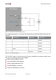
Signal
Description
EcuControl_AwakeDiagActv
The UDS diagnostic session state
EcuControl_AwakeECU
The ECU awake state
Table 5-29: ECU Control Signals
Functionality
If the current UDS diagnostic session is not default the signal EcuControl_AwakeDiagActv
is set to active.
The signal EcuControl_AwakeECU is set to active if
DiagnosticCAN_State is active or
J1939CAN_State is active
5.4.2 Real-Time Clock
Signal
Description
RTC_TimerValue
The real-time clock timer start value in minutes
RTC_TimerRequest
The real-time clock timer start trigger
RTC_Wakeup
The real-time clock wakeup state
RTC_TimerStatus
The real-time clock timer state
Table 5-30 Real-time Clock Signals
Functionality
A real-time clock, which supports to notify or wakeup the microcontroller after a defined time
or at a defined time, can be programmed via CAN.