
User's Manual

User Manual VC-EVCC
© 2021 Vector Informatik GmbH Version 1.3.0 169
Caution
The software of the VC-EVCC cannot be used with the hardware of the VC-VCCU or
the VC-EVCC-P.
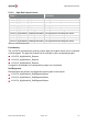
5.3.3 Outputs
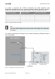
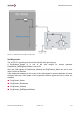
5.3.3.1 LED Control
Signal
Description
VCVCCU_LED0_Request
The LED0 duty cycle percentage
VCVCCU_LED1_Request
The LED1 duty cycle percentage
VCVCCU_LED2_Request
The LED2 duty cycle percentage
VCVCCU_LED0_SelfDiagnosticStatus
The LED0 self-diagnostic status
VCVCCU_LED1_SelfDiagnosticStatus
The LED1 self-diagnostic status
VCVCCU_LED2_SelfDiagnosticStatus
The LED2 self-diagnostic status
Table 5-27 LED Outputs Signals
Functionality
The LED outputs can be controlled by setting the following signals via CAN,
VCVCCU_LED0_Request, VCVCCU_LED1_Request and VCVCCU_LED2_Request. If
one of the signals is not available, the respective LED output is not controlled.
Self-Diagnostic
Electrical faults are stored in the following signals representing the three different outputs:
LED0_SelfDiagnosticStatus
LED1_SelfDiagnosticStatus
LED2_SelfDiagnosticStatus