
User's Manual

User Manual VC-EVCC
© 2021 Vector Informatik GmbH Version 1.3.0 167
5.3.2.3 Digital Input (Generic Switch)
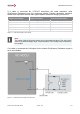
One high side output of the VC-EVCC is implemented to work as an input.
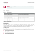
Signal
Description
HighSideOut2_Input_Status
The HSOUT2 input value
Table 5-22 Analog Inputs Signals
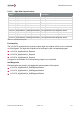
The following table shows the implemented hysteresis for the detection of a pressed button
event.
Input voltage level
HighsideOut2_InputStatus
≥ 4500 mV
pressed
≤ 3500 mV
not pressed
≥ 3500 mV ≤ 4500 mV
Remain present value
Initial value
Signal not available
Table 5-23 Button Hysteresis
Note
Self-diagnostics is not supported for this input.
5.3.2.4 Terminal 15 Signal Input
Signal
Description
HighSideOut3_Input_Status
The high side out 3 input value:
HighSideOut3_Input_Wakeup
The high side out 3 wakeup status
Table 5-24 Terminal 15 Input Signals
The following table shows the implemented hysteresis for Terminal 15 signal Input.
Input voltage level
HighsideOut3_InputStatus
≥ 4500 mV
Pressed (active)
≤ 3500 mV
not pressed (inactive)
≥ 3500 mV ≤ 4500 mV
Remain present value
Initial value
Signal not available
Table 5-25 Terminal 15 Signal Hysteresis
If the Terminal 15 signal input is the source for a wakeup event the information is stored in
the signal HighSideOut3_Input_Wakeup.