
User's Manual

User Manual VC-EVCC
© 2021 Vector Informatik GmbH Version 1.3.0 164
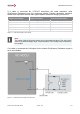
5.3.1.2 Control Pilot Evaluation
The control pilot signal is a low-level communication between the charging infrastructure
and the VC-EVCC based on the voltage level, the duty cycle and the period of the Control
Pilot signal.
Signal
Description
ControlPilot_Frequency
The period of the control pilot signal
ControlPilot_DutyCycle
The duty cycle of the control pilot signal
ControlPilot_Voltage
The voltage level of the control pilot signal
ControlPilot_Wakeup
The wakeup state of the control pilot signal
ControlPilot_ChargeMode
The requested control pilot charge mode (via CAN)
Table 5-17 Control Pilot Evaluation Signals
Functionality
The VC-EVCC detects a wakeup on the control pilot line in the first 75ms after the wakeup
event and sets the signal ControlPilot_Wakeup.
Frequency, duty cycle and voltage level are measured or set to a specific value according
to the following logic. Also, the state of the control pilot communication is set.
If the measured frequency (ControlPilot_Frequency) is within the range of 800Hz - 1200Hz
the Control Pilot communication may be ready (active). If the measured frequency is outside
this range the communication is not ready (inactive).
> If the communication is ready the VC-EVCC measures the duty cycle
(ControlPilot_DutyCycle) of the signal.
> If the communication is not ready or the measured frequency is 0Hz
ControlPilot_DutyCycle is set to signal not available.
> If the communication is ready or the frequency is 0 Hz the voltage level
ControlPilot_Voltage of the control pilot signal is measured.
> If the communication is not ready and the frequency is > 0 Hz the ControlPilot_Voltage
is set to signal not available.
Self-Diagnostic
The hardware circuit of the VC-EVCC supports to detect a short to battery fault at the control
pilot pin.
If the control pilot frequency is 0 Hz and the voltage is in its defined range for short to battery
detection the VC-EVCC sets the duty cycle signal and the frequency signal to error value
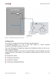
5.3.1.3 Protective Earth
The VC-EVCC measures the Protective Earth (PE) to GND offset voltage at the
microcontroller pins. If the offset voltage exceeds the respective minimum or maximum limit
the VC-EVCC will raise the following diagnostic trouble code.
Protective Earth (PE) to GND offset out of range (DTC 0x2BE0E2)