VC-EVCC User Manual Version 1.3.
User Manual VC-EVCC Document Information History Author Date Version Remarks vml 2021-05-18 1.0.0 Initial document vml/ssm 2021-05-25 1.1.0 Chapter 1.3 Product Compliance: Links updated Chapter 1.7 Safety Instructions and Hazard Warnings: Danger note updated Chapter 4.3 ECU Interface Characteristics: Table updated sng 2021-07-16 1.2.0 Chapter 1.3 Product Compliance: Note added reg. conducted CE/ UKCA certification tests sng/dim 2021-08-11 1.3.0 Chapter 1.
User Manual VC-EVCC Contents 1 Introduction .................................................................................................................... 8 1.1 About This Manual ................................................................................................... 8 1.2 Management Standards ........................................................................................... 9 1.3 Product Compliance .................................................................................
User Manual VC-EVCC 5.5.3 Plug Unlocking ............................................................................................ 175 5.5.4 Control Pilot Handling.................................................................................. 176 5.5.5 Digital Input Control ..................................................................................... 178 5.5.6 Temperature Control ................................................................................... 179 5.5.
User Manual VC-EVCC 7 Mechanical Characteristics ....................................................................................... 226 7.1 Connector ............................................................................................................ 226 8 Device Installation ...................................................................................................... 227 9 Support, Aftersales, Return Material and Replacement .......................................... 229 9.
User Manual VC-EVCC Illustrations Figure 1-1 Figure 1-2 Figure 1-3 Figure 1- 4 Figure 1-5 Figure 2-1 Figure 3-1 Figure 4-1 Figure 5-1: Figure 5-2: Figure 5-3: Figure 5-4: Figure 6-1 Figure 6-2: Figure 6-3: Figure 8-1: Figure 8-2: Figure 10-1 CE Mark on Product Label ........................................................................ 11 WEEE Mark on Product Label .................................................................. 11 UKCA Mark on Product Label ...........................................
User Manual VC-EVCC Table 5-27 Table 5-28 Table 5-29: Table 5-30 Table 5-31 Table 5-32 Table 5-33 Table 5-34 Table 5-35 Table 5-36 Table 5-37 Table 5-38 Table 5-39 Table 5-40 Table 5-41 Table 5-42 Table 5-43 Table 5-44 Table 5-45 Table 5-46 Table 5-47 Table 5-48 Table 5-49 Table 5-50 Table 5-51 Table 5-52 Table 5-53 Table 5-54 Table 5-55 Table 5-56 Table 5-57 Table 5-58 Table 5-59 Table 5-60 Table 5-61 Table 5-62 Table 5-63 Table 5-64 Table 5-65 Table 5-66 Table 5-67 Table 5-68 Table 5-69: Table 7-1 Table
User Manual VC-EVCC 1 Introduction This chapter contains relevant information about Product Compliance, Warranty and Safety Instructions. Observe all local and regional laws and regulations as well as the safety regulations mentioned in this document. This Manual is valid for the VC-EVCC and the related product variants (trade names): > VC-EVCC Series > VC-EVCC Evaluation In the following all product variants are referred to as VC-EVCC unless expressly stated otherwise. 1.
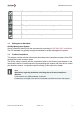
User Manual VC-EVCC This symbol indicates that you must not change these files. This symbol indicates that multimedia files are available. This symbol indicates where introductory information is available. This symbol indicates where basic knowledge is available. This symbol indicates where expert knowledge is available. This symbol indicates changes in the manual. 1.
User Manual VC-EVCC Note Restrictions due to Product Compliance Reasons This restriction is solely valid for evaluation-devices “VC-EVCC Evaluation”. The length of cables connected to the following pins is restricted to a maximal length of 3m: LED0, LED1, LED2, LED_GND, VCC_SS, SS_GND, DIN, DIN_GND, HS_OUT0, HS_OUT1, HS_OUT2, HS_OUT4 (see Chapter 10.1). The usage of the fitting wiring harness provided by Vector or a wiring harness with comparable technical properties is strongly recommended.
User Manual VC-EVCC 1.3.1 EU: Applied Regulations & Restrictions of Use CE Conformity (EU Product Conformity) according to Regulation (EC) 765/2008 This section is solely valid for evaluation-devices “VC-EVCC Evaluation”. For the concretely applied regulations and standards of this scope see “EU Declaration of conformity” of this device.
User Manual VC-EVCC 1.3.3 USA: Applied Regulations & Restrictions of Use FCC Conformity - Certification according to FCC Part 15 This section is solely valid for evaluation-devices “ VC-EVCC Evaluation”. This ECU has been certified as Part 15 Class B Digital Device by the Federal Communications Commission of the U.S. Government through following FCC ID: 2AXYRVCEVCC. For Details see “FCC certification” of this device.
User Manual VC-EVCC 1.3.4 Canada: Applied Regulations & Restrictions of Use ISED Conformity (ICES-003) This section is solely valid for evaluation-devices “ VC-EVCC Evaluation”. This ECU represents a Category II equipment and therefore is exempt from certification and registration. To represent Vector´s Supplier's Declaration of Conformity (SDoC) with ISED requirements the ISED compliance label is placed on each unit of this device.
User Manual VC-EVCC Caution This ECU is released as a safety element out of context according to the ISO 26262. The OEM is responsible for the entire vehicle safety concept and must take into account the dedicate Safety Manual [TBD] during the development and commissioning process in order to fulfill the standard and regulatory requirements. Caution The ECU may only be operated according to the instructions and descriptions of this manual.
User Manual VC-EVCC Danger Explosion due to operation of electric devices in potentially explosive atmospheres. Serious injury or death. > Observe the applicable regulations and precautionary measures for explosive environments. Warning Overload damage due to fault. Serious injury or death. > Protect the DC power supply circuit with a 15 A circuit breaker (or smaller) in the installation in order to limit the power in case of a fault. Warning Hot surfaces or moving parts due to actuated loads.
User Manual VC-EVCC Note Property Damage > The device must be installed, connected and commissioned by a qualified and trained person. > Disconnect the device from all connections before handling it. > Disconnect all independently supplied power circuits. > The degree of protection IP6K6K, IP6K7 and IP6K9K can only be guaranteed when all connections of the device are fitted with connectors with the same protection degree.
User Manual VC-EVCC 2 General The Vector Controller – Electric Vehicle Communication Controller (VC-EVCC) is a generic ECU for 24V environments. It realizes electrical charging according to DIN SPEC 70121 see [1] and ISO15118 see [5] for power line communication (PLC) with the infrastructure. The Hardware basis is the VP-EVCC with an integrated flash bootloader. The VC-EVCC includes a modern MICROSAR stack with all relevant application modules to realize electrical charging communication.
User Manual VC-EVCC 3 System Architecture The VC-EVCC is designed to be integrated into the vehicle with the following system architecture. The VC-EVCC supports either the combined charging system (CCS) combo 1 or combo 2 inlets according to the charging standards [10] and [4]. The supported charging standard is configurable via software. Figure 3-1 3.
User Manual VC-EVCC Caution The Phoenix Inlets CHARX T1HBI12 and CHARX T2HBI12 (Generation 4) use a different PT1000 characteristic curve than implemented within the VC-EVCC. As a result, the VC-EVCC will not stop charging at the critical temperature of 90°C. Instead, the vehicle must monitor the resistance values of PTC1 and PTC2 which are transmitted on the J1939 vehicle CAN. The vehicle is responsible to stop charging once a temperature of 90°C is reached.
User Manual VC-EVCC 4 ECU This chapter contains an overview about the VC-EVCC. The electrical and mechanical characteristics of the VC-EVCC are part of this User Manual. 4.1 ECU Overview The following diagram and tables give an abstract overview of the interfaces of the hardware. Note There are many different configuration options for the hardware of the VC-EVCC. The following figure shows the configuration of the VC-EVCC. Figure 4-1 VC-EVCC Interfaces © 2021 Vector Informatik GmbH Version 1.3.
User Manual VC-EVCC 4.2 Key ECU Characteristics Parameter Description CPU SPC564B74L7, 120MHz Memory 3,0 MB Code-Flash, 4x16 kB Data-Flash, 192 kB RAM Voltage range 8V … 32V (ISO 16750, Code E) Overvoltage 2 min 48V Connector Molex CMC36 Hybrid Sealed (36 Pins) Communication 3x CAN 2.0B (incl.
User Manual VC-EVCC 3 Analog Input PT1000 PT1000 temperature sensor input 3 20mA LED Output Constant current output for LEDs > PWM dimming > Static digital 1 Latch Position Input Analog input to read a resistor value coded latch or switch 1 Digital Input 0…UBat Wake-up capable input 3 200mA High-Side Output Low power 24V output > PWM > Static digital 1 Wake-up Input Terminal 15 wake-up line.
User Manual VC-EVCC 5 Detailed Functional Description 5.1 J1939 CAN Signal Description WakeupRsn_VCVCCU The wakeup reason of the VC-EVCC Table 5-1 J1939 CAN Signals Functionality CAN channel CAN1 is the J1939 vehicle CAN. The baud rate is set to 250kBit/s but can be configured through the diagnostic channel. At each reboot, the VC-EVCC checks the stored parameter for the configuration and adjusts itself automatically. The configuration needs to be done only once.
User Manual VC-EVCC Communication via vehicle coupler (Control Pilot State B2) Caution The VC-EVCC is intended to be used with network management. Therefore, the CAN message “NM_CGW” must be sent by the vehicle in order to ensure full functionality. The recommend cycle time is 100 ms. The value of the included signal “WakeupRsn_CGW” is not relevant and can be determined by the user. Note Connecting clamp 30 causes a wakeup of the VC-EVCC. After startup the VC-EVCC stays always awake for 60 seconds. 5.
User Manual VC-EVCC stop sending certain CAN messages. Please refer to the chapter “UDS communication” for more information about configurable message cycle times. 5.1.2 End-to-End Protection of CAN Messages The VC-EVCC uses the MICROSAR Safe End-to-End (E2E) for protection of the CAN messages VCVCCU_ChargeFromVehicle and VCVCCU_ChargeToVehicle. The E2E Profile 1 is used to encode and decode the exchanged data.
User Manual VC-EVCC 5.1.2.2 VCVCCU_ChargeToVehicle The CAN message VCVCCU_ChargeToVehicle contains the following signals which are used for E2E protection. E2E_Cnt_ChargeToVehicle (Counter): This signal is used to ensure the data is received periodically. The VC-EVCC increments the value of this signal for every message cycle until it reaches 0x0E after which it is reset to 0x0. Then incrementing will be started again. E2E_CRC_ChargeToVehicle: This signal is used to ensure the data validity.
User Manual VC-EVCC 5.2 Diagnostic CAN Signal Description DiagnosticCAN_Wakeup The wakeup state of the Diagnostic CAN DiagnosticCAN_BusOff The bus off state of the Diagnostic CAN DiagnosticCAN_WakeupRsn The wakeup reason of the Diagnostic CAN DiagnosticCAN_State The state of the Diagnostic CAN Table 5-3 Diagnostic CAN Internal Signals Functionality CAN channel CAN0 is a diagnostic related CAN supporting the UDS protocol. The baud rate is set to 500kBaud.
User Manual VC-EVCC DID FD 06 – Configuration PTC2 message DID FD 07 – Configuration InletStatus message DID FD 08 – Configuration ControlPilotStatus message DID FD 09 – Configuration InternalVoltageStatus message DID FD 0A – Configuration InternalVoltageRawValues message DID FD 0B – Configuration InletStatus2 message StopCharge CAN signal DID FD 13 – Configuration StopCharge CAN Signal Activation Charging arbitration DID FD 0F – Configuration Primary J1939 Source Address DID FD 10 – Co
User Manual VC-EVCC 5.2.1.2 Configuration of ECU parameters The configuration of ECU parameters can be executed with the Vector tools CANoe or CANalyzer. Alternatively, the configuration can be executed manually. The configuration of ECU parameters with CANoe/CANalyzer is handled within the Diagnostic Console. The following steps lead to the Diagnostic Console within CANoe/CANalyzer. 1. Start CANoe/CANalyzer and open the delivered CANoe/CANalyzer configuration “VC-EVCC”.
User Manual VC-EVCC 2. Click on the desktop “Diagnostic”. The desktop “Diagnostic” contains the window “VCEVCC Diagnostic Console”. Please note that not all versions of CANoe/CANalyzer include the Diagnostic Console. The detailed description of the configuration of individual parameters is described in the following chapters. Please note that the measurement must be started to execute configuration of ECU parameters. © 2021 Vector Informatik GmbH Version 1.3.
User Manual VC-EVCC 5.2.1.2.1 Configuration of CAN1 – J1939 CAN Baud Rate It is possible to configure the baud rate of the VC-EVCC for the J1939 vehicle CAN. By using the diagnostic service “Read Data By Identifier” (0x22) – DID 0xFD00 it is possible to read the current configured J1939 CAN baud rate. By using the diagnostic service “Write Data By Identifier” (0x2E) – DID 0xFD00 it is possible to write the J1939 CAN baud rate.
User Manual VC-EVCC Configuration with CANoe/CANalyzer The configuration of the J1939 CAN Baud rate can be executed with CANoe/CANalyzer according to the following description. 1. Select the tab “Sessions” and click on “10 03 – Extended Diagnostic Session Start”. Click on the button “Execute” to start the Extended Diagnostic Session. Please note that the response must be positive. 2. Select the tab “Stored Data” and click on “2E FD 00 – VCVCCU Configuration J1939 CAN Write”.
User Manual VC-EVCC 3. By executing the command “22 FD 00 – VCVCCU Configuration J1939 CAN Read” the current configuration of the baud rate can be verified. © 2021 Vector Informatik GmbH Version 1.3.
User Manual VC-EVCC Configuration with Indigo The configuration of the J1939 CAN Baud rate can be executed with Indigo according to the following description. 1. Select the tab “Parametrizer” and click on the field Value of the VC-EVCC application “VCVCCU Configuration J1939 CAN/J1939 CAN Configuration/J1939 CAN Baud Rate”. Select the requested Baud rate and click on the button “Write” to execute the configuration. © 2021 Vector Informatik GmbH Version 1.3.
User Manual VC-EVCC Manual Configuration Reprogramming is also possible without CANoe/CANalyzer. In this case, the following CAN Messages (UDS/ TP) must be sent on the diagnostic CAN (CAN0) manually: CAN-Identifier: Tester --> VC-EVCC, Request: 0x610 VC-EVCC --> Tester, Response: 0x612 Tester --> Functional: 0x614 1. Extended Session: Request: 02 10 03 FF FF FF FF FF Response: 06 50 03 00 32 01 F4 FF 2.
User Manual VC-EVCC 5.2.1.2.2 Configuration of HSOUT0 The VC-EVCC gives the possibility to enable an output at startup to wake-up other ECUs. The behavior can be configured. By using the diagnostic service “Read Data By Identifier” (0x22) – DID 0xFD03 it is possible to read the current configuration of the HSOUT0. By using the diagnostic service “Write Data By Identifier” (0x2E) – DID 0xFD03 it is possible to write the configuration of the HSOUT0.
User Manual VC-EVCC If value 0x03 is configured the HSOUT0 will be enabled with respect to CP and PP according to the following table: Signal Source Value HSOUT0 VCVCCU_ControlPilot_DutyCycle SNA && Not_connected Not_pressed VCVCCU_ControlPilot_DutyCycle SNA && Pressed VCVCCU_PlugPresent_Status Connected || Error || SNA VCVCCU_ControlPilot_DutyCycle 1% - 99% || Error && Not_connected Pressed 1% - 99% || Error && Connected || Error || SNA Pressed VCVCCU_PlugPresent_Status VCVCCU_PlugPresent
User Manual VC-EVCC Configuration with CANoe/CANalyzer The configuration of the HSOUT0 can be executed with CANoe/CANalyzer according to the following description. 1. Select the tab “Sessions” and click on “10 03 – Extended Diagnostic Session Start”. Click on the button “Execute” to start the Extended Diagnostic Session. Please note that the response must be positive. © 2021 Vector Informatik GmbH Version 1.3.
User Manual VC-EVCC 2. Select the tab “Stored Data” and click on “2E FD 03 – VCVCCU Configuration HSOUT0 Write”. Please choose the requested mode as well as the requested time period (only possible in mode “Limited on”) and click on the button “Execute”. Please note that the response must be positive. 3. By executing the command “22 FD 03 – VCVCCU Configuration HSOUT0 Read” the current configuration of the HSOUT0 can be verified. © 2021 Vector Informatik GmbH Version 1.3.
User Manual VC-EVCC Configuration with Indigo The configuration of the HSOUT0 can be executed with Indigo according to the following description. 1. Select the tab “Parametrizer” and click on the data field Value of the VC-EVCC application “VCVCCU Configuration HSOUT0/HSOUT0 Configuration/HSOUT0 Mode”. Select the requested HSOUT0 configuration and click on the button “Write” to execute the configuration.
User Manual VC-EVCC Manual Configuration Reprogramming is also possible without CANoe/CANalyzer. In this case, the following CAN Messages (UDS/ TP) must be sent on the diagnostic CAN (CAN0) manually: CAN-Identifier: Tester --> VC-EVCC, Request: 0x610 VC-EVCC --> Tester, Response: 0x612 Tester --> Functional: 0x614 1. Extended Session: Request: 02 10 03 FF FF FF FF FF Response: 06 50 03 00 32 01 F4 FF 2.
User Manual VC-EVCC 5.2.1.2.3 Configuration of High Side Output Diagnostic Mode The VC-EVCC provides the possibility to activate or deactivate the active off-state diagnostics of the HSOUT0, HSOUT1 and HSOUT4. If the active off-state diagnostic is configured as “On” the VC-EVCC will detect ShortToGnd and OpenLoad faults even if the corresponding HSOUT is disabled. The service structure is defined as 1 byte. Bit Pos.
User Manual VC-EVCC Configuration with CANoe/CANalyzer The configuration of the High Side Output diagnostic mode can be executed with CANoe/CANalyzer according to the following description. 1. Select the tab “Sessions” and click on “10 03 – Extended Diagnostic Session Start”. Click on the button “Execute” to start the Extended Diagnostic Session. Please note that the response must be positive. © 2021 Vector Informatik GmbH Version 1.3.
User Manual VC-EVCC 2. Select the tab “Stored Data” and click on “2E FD 25 – VCVCCU Configuration HSOUT diagnostic mode Write”. Please choose the requested HSOUT diagnostic mode configuration and click on the button “Execute”. Please note that the response must be positive. © 2021 Vector Informatik GmbH Version 1.3.
User Manual VC-EVCC 3. By executing the command “22 FD 25 – VCVCCU Configuration HSOUT diagnostic mode Read” the current HSOUT diagnostic mode configuration can be verified. © 2021 Vector Informatik GmbH Version 1.3.
User Manual VC-EVCC Configuration with Indigo The configuration of the HSOUT diagnostic mode can be executed with Indigo according to the following description. 1. Select the tab “Parametrizer” and click on the data field Value of the requested High Side Output (HSOUT0, HSOUT1 or HSOUT4). Select the requested HSOUT diagnostic mode configuration (“on” or “off”) and click on the button “Write” to execute the configuration. © 2021 Vector Informatik GmbH Version 1.3.
User Manual VC-EVCC Manual Configuration Reprogramming is also possible without CANoe/CANalyzer. In this case, the following CAN Messages (UDS/ TP) must be sent on the diagnostic CAN (CAN0) manually: CAN-Identifier: Tester --> VC-EVCC, Request: 0x610 VC-EVCC --> Tester, Response: 0x612 Tester --> Functional: 0x614 1. Extended Session: Request: 02 10 03 FF FF FF FF FF Response: 06 50 03 00 32 01 F4 FF 2.
User Manual VC-EVCC 5.2.1.2.4 Configuration of Message Cycle Times The VC-EVCC provides the possibility to configure message cycle times of certain CAN messages of the J1939 database.
User Manual VC-EVCC Configuration with CANoe/CANalyzer The configuration of message cycle times can be executed with CANoe/CANalyzer according to the following description. 1. Select the tab “Sessions” and click on “10 03 – Extended Diagnostic Session Start”. Click on the button “Execute” to start the Extended Diagnostic Session. Please note that the response must be positive. 2. Select the tab “Stored Data” and select the message whose cycle time should be configured.
User Manual VC-EVCC 3. By executing the “Read”-command of the corresponding message the current configuration of the message cycle time can be verified. © 2021 Vector Informatik GmbH Version 1.3.
User Manual VC-EVCC Configuration with Indigo The configuration of message cycle times can be executed with Indigo according to the following description. 1. Select the tab “Parametrizer” and click on the data field Value of the message to be configured, for example “VCVCCU Configuration PTC0 message/Time Period”. Enter the requested message cycle time and click on the button “Write” to execute the configuration. © 2021 Vector Informatik GmbH Version 1.3.
User Manual VC-EVCC Manual Configuration Reprogramming is also possible without CANoe/CANalyzer. In this case, the following CAN Messages (UDS/ TP) must be sent on the diagnostic CAN (CAN0) manually: CAN-Identifier: Tester --> VC-EVCC, Request: 0x610 VC-EVCC --> Tester, Response: 0x612 Tester --> Functional: 0x614 1. Extended Session: Request: 02 10 03 FF FF FF FF FF Response: 06 50 03 00 32 01 F4 FF 2.
User Manual VC-EVCC VCVCCU_PTC1 FD 05 VCVCCU_PTC2 FD 06 VCVCCU_InletStatus FD 07 VCVCCU_ControlPilotStatus FD 08 VCVCCU_InternalVoltageStatus FD 09 VCVCCU_InternalVoltageRawValues FD 0A VCVCCU_InletStatus2 FD 0B Table 5-8 Data Identifiers for Message Cycle Time Configuration In order to read the present message cycle time configuration, the following communication has to be executed. 4.
User Manual VC-EVCC 5.2.1.2.5 Configuration of StopCharge CAN Signal The VC-EVCC provides the possibility to use the VCVCCU_Vehicle_StopCharge to stop charging and unlocking the plug. CAN-signal The service structure is defined as 1 byte. Value Description 0x00 StopCharge via CAN signal feature is deactivated (default) StopCharge via CAN signal feature is activated 0x01 Note An update of the parameter requires a reboot of the VC-EVCC to be applicable.
User Manual VC-EVCC Configuration with CANoe/CANalyzer The configuration of the StopCharge CAN signal can be executed with CANoe/CANalyzer according to the following description. 1. Select the tab “Sessions” and click on “10 03 – Extended Diagnostic Session Start”. Click on the button “Execute” to start the Extended Diagnostic Session. Please note that the response must be positive. © 2021 Vector Informatik GmbH Version 1.3.
User Manual VC-EVCC 2. Select the tab “Stored Data” and click on “2E FD 13 – VCVCCU Configuration StopCharge CAN Signal Write”. Please choose the requested StopCharge CAN Signal configuration (“on” or “off”) and click on the button “Execute”. Please note that the response must be positive. © 2021 Vector Informatik GmbH Version 1.3.
User Manual VC-EVCC 3. By executing the command “22 FD 13 – VCVCCU Configuration StopCharge CAN Signal Read” the current configuration of the StopCharge CAN Signal can be verified. © 2021 Vector Informatik GmbH Version 1.3.
User Manual VC-EVCC Configuration with Indigo The configuration of the StopCharge CAN Signal can be executed with Indigo according to the following description. 1. Select the tab “Parametrizer” and click on the data field Value of the VC-EVCC application “VCVCCU Configuration StopCharge CAN Signal/StopCharge CAN Signal Status Field/StopCharge CAN Signal Status”. Select the requested StopCharge CAN Signal configuration and click on the button “Write” to execute the configuration.
User Manual VC-EVCC Manual Configuration Reprogramming is also possible without CANoe/CANalyzer. In this case, the following CAN Messages (UDS/ TP) must be sent on the diagnostic CAN (CAN0) manually: CAN-Identifier: Tester --> VC-EVCC, Request: 0x610 VC-EVCC --> Tester, Response: 0x612 Tester --> Functional: 0x614 1. Extended Session: Request: 02 10 03 FF FF FF FF FF Response: 06 50 03 00 32 01 F4 FF 2.
User Manual VC-EVCC 5.2.1.2.6 Configuration of Primary J1939 Source Address (Charging Arbitration) The VC-EVCC provides the possibility to configure the Primary J1939 Source Address.
User Manual VC-EVCC Configuration with CANoe/CANalyzer The configuration of the Primary J1939 Source Address can be executed with CANoe/CANalyzer according to the following description. 1. Select the tab “Sessions” and click on “10 03 – Extended Diagnostic Session Start”. Click on the button “Execute” to start the Extended Diagnostic Session. Please note that the response must be positive. © 2021 Vector Informatik GmbH Version 1.3.
User Manual VC-EVCC 2. Select the tab “Stored Data” and click on “2E FD 0F – VCVCCU Configuration Primary J1939 Source Address Write”. Please choose the requested Primary Source Address and click on the button “Execute”. Please note that the response must be positive. © 2021 Vector Informatik GmbH Version 1.3.
User Manual VC-EVCC 3. By executing the command “22 FD 0F – VCVCCU Configuration Primary J1939 Source Address Read” the current Primary Source Address can be verified. © 2021 Vector Informatik GmbH Version 1.3.
User Manual VC-EVCC Configuration with Indigo The configuration of the Primary J1939 Source Address can be executed with Indigo according to the following description. 1. Select the tab “Parametrizer” and click on the data field Value of the VC-EVCC application “VCVCCU Configuration Primary J1939 Source Address/Primary Source Address”. Select the requested Primary J1939 Source Address and click on the button “Write” to execute the configuration. © 2021 Vector Informatik GmbH Version 1.3.
User Manual VC-EVCC Manual Configuration Reprogramming is also possible without CANoe/CANalyzer. In this case, the following CAN Messages (UDS/ TP) must be sent on the diagnostic CAN (CAN0) manually: CAN-Identifier: Tester --> VC-EVCC, Request: 0x610 VC-EVCC --> Tester, Response: 0x612 Tester --> Functional: 0x614 1. Extended Session: Request: 02 10 03 FF FF FF FF FF Response: 06 50 03 00 32 01 F4 FF 2.
User Manual VC-EVCC 5.2.1.2.7 Configuration of Secondary J1939 Source Address (Charging Arbitration) The VC-EVCC provides the possibility to configure the Secondary J1939 Source Address.
User Manual VC-EVCC Configuration with CANoe/CANalyzer The configuration of the Secondary J1939 Source Address can be executed with CANoe/CANalyzer according to the following description. 1. Select the tab “Sessions” and click on “10 03 – Extended Diagnostic Session Start”. Click on the button “Execute” to start the Extended Diagnostic Session. Please note that the response must be positive. © 2021 Vector Informatik GmbH Version 1.3.
User Manual VC-EVCC 2. Select the tab “Stored Data” and click on “2E FD 10 – VCVCCU Configuration Secondary J1939 Source Address Write”. Please choose the requested Secondary Source Address and click on the button “Execute”. Please note that the response must be positive. © 2021 Vector Informatik GmbH Version 1.3.
User Manual VC-EVCC 3. By executing the command “22 FD 10 – VCVCCU Configuration Secondary J1939 Source Address Read” the current Secondary Source Address can be verified. © 2021 Vector Informatik GmbH Version 1.3.
User Manual VC-EVCC Configuration with Indigo The configuration of the Secondary J1939 Source Address can be executed with Indigo according to the following description. 2. Select the tab “Parametrizer” and click on the data field Value of the VC-EVCC application “VCVCCU Configuration Secondary J1939 Source Address/Secondary Source Address”. Select the requested Secondary J1939 Source Address and click on the button “Write” to execute the configuration. © 2021 Vector Informatik GmbH Version 1.3.
User Manual VC-EVCC Manual Configuration Reprogramming is also possible without CANoe/CANalyzer. In this case, the following CAN Messages (UDS/ TP) must be sent on the diagnostic CAN (CAN0) manually: CAN-Identifier: Tester --> VC-EVCC, Request: 0x610 VC-EVCC --> Tester, Response: 0x612 Tester --> Functional: 0x614 1. Extended Session: Request: 02 10 03 FF FF FF FF FF Response: 06 50 03 00 32 01 F4 FF 2.
User Manual VC-EVCC 5.2.1.2.8 Configuration of Charge Node Selection (Charging Arbitration) The VC-EVCC provides the possibility to use charging arbitration which enables to run two VC-EVCCs with different source addresses on the same CAN channel. The service structure is defined as 1 byte. Value Description 0x00 Charging Arbitration is inactive (default) Charging Arbitration is active 0x01 Note An update of the parameter requires a reboot of the VC-EVCC to be applicable.
User Manual VC-EVCC Configuration with CANoe/CANalyzer The configuration of the Charge Node Selection can be executed with CANoe/CANalyzer according to the following description. 1. Select the tab “Sessions” and click on “10 03 – Extended Diagnostic Session Start”. Click on the button “Execute” to start the Extended Diagnostic Session. Please note that the response must be positive. © 2021 Vector Informatik GmbH Version 1.3.
User Manual VC-EVCC 2. Select the tab “Stored Data” and click on “2E FD 14 – VCVCCU Configuration Charge Node Selection Write”. Please choose the requested Charge Node Selection (“on” or “off”) and click on the button “Execute”. Please note that the response must be positive. © 2021 Vector Informatik GmbH Version 1.3.
User Manual VC-EVCC 3. By executing the command “22 FD 14 – VCVCCU Configuration Charge Node Selection Read” the current configuration of the Charge Node Selection can be verified. © 2021 Vector Informatik GmbH Version 1.3.
User Manual VC-EVCC Configuration with Indigo The configuration of Charge Node Selection can be executed with Indigo according to the following description. 3. Select the tab “Parametrizer” and click on the data field Value of the VC-EVCC application “VCVCCU Configuration Charge Node Selection/Charge Node Selection Status Field/Charge Node Selection Status”. Select the requested Charge Node Selection configuration and click on the button “Write” to execute the configuration.
User Manual VC-EVCC Manual Configuration Reprogramming is also possible without CANoe/CANalyzer. In this case, the following CAN Messages (UDS/ TP) must be sent on the diagnostic CAN (CAN0) manually: CAN-Identifier: Tester --> VC-EVCC, Request: 0x610 VC-EVCC --> Tester, Response: 0x612 Tester --> Functional: 0x614 1. Extended Session: Request: 02 10 03 FF FF FF FF FF Response: 06 50 03 00 32 01 F4 FF 2.
User Manual VC-EVCC 5.2.1.2.9 Configuration of Transport Layer Security – V2G The VC-EVCC provides the possibility to establish a secure connection to the EVSE using Transport Layer Security (TLS) for V2G communication. © 2021 Vector Informatik GmbH Version 1.3.
User Manual VC-EVCC Configuration with CANoe/CANalyzer The configuration of TLS (V2G) can be executed with CANoe/CANalyzer according to the following description. 1. The configuration of TLS requires the diagnostic services “Extended Session” and “Security Access”. Therefore, select the window “VCVCCU – Diagnostic Session Control” and double-click on “Extended Session Start”. Continue by double-clicking on “[Level 0x01] Request Seed (level 1) Request”. Please note that the responses must be positive.
User Manual VC-EVCC 2. To use TLS a certificate must be written. Therefore, select the window “VCVCCU – Diagnostic Console” and select the tab “Stored Data”. Click on “2E FD 0D – VCVCCU Configuration TLS Certificate Write”. Write the requested certificate (800 bytes) and click on “Execute”. Please note that the response must be positive. 3. Select the tab “Stored Data” and click on “2E FD 0C – VCVCCU Configuration TLS Activation Write”.
User Manual VC-EVCC 4. By executing the command “22 FD 0C – VCVCCU Configuration TLS Activation Read” the current configuration of TLS can be verified. © 2021 Vector Informatik GmbH Version 1.3.
User Manual VC-EVCC Configuration with Indigo The configuration of TLS (V2G) can be executed with Indigo according to the following description. 1. Select the tab “VC-VCCU-VAS” and click on the empty data field of V2G. Select the requested TLS certificate and click on the button “Write” to execute the configuration. After the successful writing of the TLS certificate a notification shows up in the field “Information”. © 2021 Vector Informatik GmbH Version 1.3.
User Manual VC-EVCC 2. Select the tab “Parametrizer” and click on the data field Value of the VC-EVCC application “VCVCCU Configuration TLS Activation/TLS Activation Status Field/TLS Activation Status”. Select the requested TLS Activation configuration and click on the button “Write” to execute the configuration. © 2021 Vector Informatik GmbH Version 1.3.
User Manual VC-EVCC Manual Configuration Reprogramming is also possible without CANoe. In this case, the following CAN Messages (UDS/ TP) must be sent on the diagnostic CAN (CAN0) manually: CAN-Identifier: Tester --> VC-EVCC, Request: 0x610 VC-EVCC --> Tester, Response: 0x612 Tester --> Functional: 0x614 1. Extended Session: Request: 02 10 03 FF FF FF FF FF Response: 06 50 03 00 32 01 F4 FF 2.
User Manual VC-EVCC Note This description does not include all request/response-messages due to the size of the TLS certificate (800 byte). In order to write the TLS certificate correctly the transport protocol according to ISO 15765-2 [6] has to be implemented. The following response indicates a successful writing of the TLS certificate. Response: 03 6E FD 0D FF FF FF FF 6.
User Manual VC-EVCC 5.2.1.2.10 Configuration of Transport Layer Security – VAS The VC-EVCC provides the possibility to establish a secure connection to the EVSE using Transport Layer Security (TLS) for Value Added Services. © 2021 Vector Informatik GmbH Version 1.3.
User Manual VC-EVCC Configuration with CANoe/CANalyzer The configuration of TLS (VAS) can be executed with CANoe/CANalyzer according to the following description. 1. The configuration of TLS requires the diagnostic services “Extended Session” and “Security Access”. Therefore, select the window “VCVCCU – Diagnostic Session Control” and double-click on “Extended Session Start”. Continue by double-clicking on “[Level 0x01] Request Seed (level 1) Request”. Please note that the responses must be positive.
User Manual VC-EVCC 2. To use TLS a certificate must be written. Therefore, select the window “VCVCCU – Diagnostic Console” and select the tab “Stored Data”. Click on “2E FD 12 – VCVCCU Configuration TLS Certificate2 Write”. Write the requested certificate (800 bytes) and click on “Execute”. Please note that the response must be positive. 3. Select the tab “Stored Data” and click on “2E FD 0C – VCVCCU Configuration TLS Activation Write”.
User Manual VC-EVCC 4. By executing the command “22 FD 0C – VCVCCU Configuration TLS Activation Read” the current configuration of TLS can be verified. © 2021 Vector Informatik GmbH Version 1.3.
User Manual VC-EVCC Configuration with Indigo The configuration of TLS (VAS) can be executed with Indigo according to the following description. 1. Select the tab “VC-VCCU-VAS” and click on the empty data field of V2ICP. Select the requested TLS certificate and click on the button “Write” to execute the configuration. After the successful writing of the TLS certificate a notification shows up in the field “Information”. © 2021 Vector Informatik GmbH Version 1.3.
User Manual VC-EVCC 2. Select the tab “Parametrizer” and click on the data field Value of the VC-EVCC application “VCVCCU Configuration TLS Activation/TLS Activation Status Field/TLS Activation Status”. Select the requested TLS Activation configuration and click on the button “Write” to execute the configuration. © 2021 Vector Informatik GmbH Version 1.3.
User Manual VC-EVCC 5.2.1.2.11 Configuration of Value Added Services The VC-EVCC provides the usage of Value Added Service (VAS) according to the VDV 261 specification. In order to use Value Added Service TLS must be activated. Configuration with CANoe/CANalyzer The configuration of Value Added Services can be executed with CANoe/CANalyzer according to the following description.
User Manual VC-EVCC > Option1: Fixed IP Address Select the window “VCVCCU – Diagnostic Console” and select the tab “Stored Data”. Click on “2E FD 11 – VCVCCU Configuration Value Added Service Write”. Select the value “Fixed IP Address” for the field “VAS AddressType Field.VAD Address Type”. Then write the values of IPv6 Address, path, user name and password in the corresponding field. Click on “Execute” after all fields are filled out. Please note that the response must be positive.
User Manual VC-EVCC Configuration with Indigo The configuration of TLS (V2G) can be executed with Indigo according to the following description. 1. Select the tab “VC-VCCU-VAS” and click on the data field “Address Type”. Select the requested Address Type configuration and enter the User Name, V2ICP URL, V2ICP Path and V2ICP Password. Click on the button “Write” to execute the configuration. After the successful writing of the TLS certificate a notification shows up in the field “Information”.
User Manual VC-EVCC 5.2.1.2.12 Configuration of Plug and Charge The VC-EVCC provides the possibility to use Plug and Charge (PnC) according to ISO 15118. The following DIDs are used for the Plug and Charge configuration of the VC-EVCC.
User Manual VC-EVCC Configuration with CANoe/CANalyzer The configuration of Plug and Charge can be executed with CANoe/CANalyzer according to the following description. 1. Select the tab “Sessions” and click on “10 03 – Extended Diagnostic Session Start”. Click on the button “Execute” to start the Extended Diagnostic Session. Please note that the response must be positive. © 2021 Vector Informatik GmbH Version 1.3.
User Manual VC-EVCC 2. Select the tab “Stored Data” and click on “2E FD 26 – VCVCCU Configuration PnC Activation Write”. Please choose the requested Plug and Charge configuration (“on” or “off”) and click on the button “Execute”. Please note that the response must be positive. © 2021 Vector Informatik GmbH Version 1.3.
User Manual VC-EVCC 3. By executing the command “22 FD 26 – VCVCCU Configuration PnC Activation Read” the current configuration of Plug and Charge can be verified. © 2021 Vector Informatik GmbH Version 1.3.
User Manual VC-EVCC Configuration with Indigo The configuration of Plug and Charge can be executed with Indigo according to the following description. 1. Select the tab “Plug and Charge” and choose the requested Plug and Charge configuration (“on” or “off”) and click on the button “Write” to execute the configuration. © 2021 Vector Informatik GmbH Version 1.3.
User Manual VC-EVCC Manual Configuration Reprogramming is also possible without CANoe/CANalyzer. In this case, the following CAN Messages (UDS/ TP) must be sent on the diagnostic CAN (CAN0) manually: CAN-Identifier: Tester --> VC-EVCC, Request: 0x610 VC-EVCC --> Tester, Response: 0x612 Tester --> Functional: 0x614 1. Extended Session: Request: 02 10 03 FF FF FF FF FF Response: 06 50 03 00 32 01 F4 FF 2.
User Manual VC-EVCC 5.2.1.2.12.2 Configuration of PnC Certificates/Private Keys The certificates and private keys for Plug and Charge can be configured via UDS as described in this chapter. Caution The stated lengths of certificates and private keys must be observed. If a certificate or a private key is shorter than the stated length the remaining bytes must be filled with zeros.
User Manual VC-EVCC Note If only one sub certificate is used, the byte arrays of the second sub certificates shall be filled with zeros. PnC Root Certificate DID FD 2F – Configuration PnC Root Certificate (800 Bytes) Configuration with CANoe/CANalyzer The configuration of PnC certificates and private keys can be executed with CANoe/CANalyzer according to the following description. Note An update of the parameter requires a reboot of the VC-EVCC to be applicable.
User Manual VC-EVCC 2. As soon as the extended session is active and the security access has been performed successfully, the configuration of certificates and private keys can be started according to the following description. Configuration of PnC Contract Certificate/Private Key: In order to configure the PnC contract certificate, select the window “VCVCCU – Diagnostic Console” and select the tab “Stored Data”. Click on “2E FD 2A – VCVCCU Configuration PnC Contract Certificate Write”.
User Manual VC-EVCC In order to configure the PnC contract certificate’s private key, select the window “VCVCCU – Diagnostic Console” and select the tab “Stored Data”. Click on “2E FD 2B – VCVCCU Configuration PnC Contract Certificate Private Key Write”. Write the requested private key (32 bytes) and click on “Execute”. Please note that the response must be positive. © 2021 Vector Informatik GmbH Version 1.3.
User Manual VC-EVCC In order to configure the PnC contract certificate and the associated private key in one step, select the window “VCVCCU – Diagnostic Console” and select the tab “Stored Data”. Click on “2E FD 2C – VCVCCU Configuration PnC Contract Certificate and Private Key Write”. Write the requested certificate and private key (832 bytes) and click on “Execute”. Please note that the response must be positive.
User Manual VC-EVCC Configuration of PnC Sub Certificates: In order to configure the PnC sub certificates, select the window “VCVCCU – Diagnostic Console” and select the tab “Stored Data”. Click on “2E FD 2D – VCVCCU Configuration PnC Sub Certificate Write”. Write the requested sub certificates (1600 bytes) and click on “Execute”. Please note that the response must be positive. © 2021 Vector Informatik GmbH Version 1.3.
User Manual VC-EVCC Configuration of PnC Root Certificate: In order to configure the PnC root certificate, select the window “VCVCCU – Diagnostic Console” and select the tab “Stored Data”. Click on “2E FD 2F – VCVCCU Configuration PnC Root Certificate Write”. Write the requested root certificate (800 bytes) and click on “Execute”. Please note that the response must be positive. © 2021 Vector Informatik GmbH Version 1.3.
User Manual VC-EVCC Configuration with Indigo The configuration of certificates and private keys for Plug and Charge can be executed with Indigo according to the following description. 1. Select the tab “Plug and Charge” and select the requested certificate/private key that shall be written. Click on the button “Write” to execute the configuration. After the successful writing of the certificate/private key a notification shows up in the field “Information”. © 2021 Vector Informatik GmbH Version 1.3.
User Manual VC-EVCC 5.2.1.2.12.3 Routine Controls for PnC Certificates/Private Keys The VC-EVCC provides several routine controls for Plug and Charge certificates/private keys. The following routine controls are available in order to validate or compare PnC certificates. Caution The execution of routine controls requires the diagnostic services “Extended Session” and “Security Access”. Otherwise, the VC-EVCC will send a negative response code.
User Manual VC-EVCC Routine Controls with CANoe/CANalyzer The routine controls of PnC certificates and private keys can be executed with CANoe/CANalyzer according to the following description. 1. The routine controls of PnC certificates and private keys require the diagnostic services “Extended Session” and “Security Access”. Therefore, select the window “VCVCCU – Diagnostic Session Control” and double-click on “Extended Session Start”.
User Manual VC-EVCC 2. As soon as the extended session is active and the security access has been performed successfully, the routine controls of certificates and private keys can be started according to the following description. Validation of OEM Provisioning or Contract Certificate: Select the tab “Routine Control” in the diagnostic console. Please choose the requested routine control for certificate validation and click on the button “Execute”. © 2021 Vector Informatik GmbH Version 1.3.
User Manual VC-EVCC Validation of Contract Certificate Signature Chain: Select the tab “Routine Control” in the diagnostic console. Please choose the requested routine control for certificate validation and enter the reference time value. Then click on the button “Execute”. © 2021 Vector Informatik GmbH Version 1.3.
User Manual VC-EVCC Comparison of PnC Certificates: Select the tab “Routine Control” in the diagnostic console. Please choose the requested routine control for certificate comparison and enter the respective certificate. If the Sub Certificate shall be compared the distance to root (0 or 1) has to be entered in the field “Distance to Root” additionally. Then click on the button “Execute”. © 2021 Vector Informatik GmbH Version 1.3.
User Manual VC-EVCC Manual Configuration Executing routine controls is also possible without CANoe. In this case, the following CAN Messages (UDS/ TP) must be sent on the diagnostic CAN (CAN0) manually: CAN-Identifier: Tester --> VC-EVCC, Request: 0x610 VC-EVCC --> Tester, Response: 0x612 Tester --> Functional: 0x614 1. Extended Session: Request: 02 10 03 FF FF FF FF FF Response: 06 50 03 00 32 01 F4 FF 2.
User Manual VC-EVCC Request: 31 01 F0 XX FF FF FF FF The following response indicates whether the certificate is valid or invalid. Response: 71 01 F0 XX XX FF FF FF XX: - 00: Valid - 01: Invalid Validation of Contract Certificate Signature Chain XX: Reference Time Value - Byte 4: Year (A raw value of 0 identifies the year 1985.
User Manual VC-EVCC Request: Response: Request: Request: … 31 01 F0 XX XX XX XX XX 30 08 14 AA AA AA AA AA 21 XX XX XX XX XX XX XX 22 XX XX XX XX XX XX XX Note This description does not include all request/response-messages due to the size of the TLS certificate (800 byte). In order to write the TLS certificate correctly the transport protocol according to ISO 15765-2 [6] has to be implemented. The following response indicates whether the certificates are identical or not identical.
User Manual VC-EVCC 5.2.1.2.13 Configuration of Charging Schedules The VC-EVCC provides the possibility to use Charging Schedules according to ISO 15118. This feature can be activated via UDS as described in this chapter. The service structure is defined as 1 byte. Value Description 0x00 Charging Schedules are deactivated (default) Charging Schedules are activated 0x01 Note An update of the parameter requires a reboot of the VC-EVCC to be applicable.
User Manual VC-EVCC Configuration with CANoe/CANalyzer The configuration of Charging Schedules can be executed with CANoe/CANalyzer according to the following description. 1. Select the tab “Sessions” and click on “10 03 – Extended Diagnostic Session Start”. Click on the button “Execute” to start the Extended Diagnostic Session. Please note that the response must be positive. © 2021 Vector Informatik GmbH Version 1.3.
User Manual VC-EVCC 2. Select the tab “Stored Data” and click on “2E FD 37 – VCVCCU Configuration Charging Schedules Activation Write”. Please choose the requested Charging Schedules configuration (“on” or “off”) and click on the button “Execute”. Please note that the response must be positive. © 2021 Vector Informatik GmbH Version 1.3.
User Manual VC-EVCC 3. By executing the command “22 FD 37 – VCVCCU Configuration Charging Schedules Activation Read” the current configuration of the Charging Schedules can be verified. © 2021 Vector Informatik GmbH Version 1.3.
User Manual VC-EVCC Configuration with Indigo The configuration of charging schedules can be executed with Indigo according to the following description. 1. Select the tab “Parametrizer” and click on the data field Value of the VC-EVCC application “VCVCCU Configuration Charging Schedules Activation/Charging Schedules Activation Status Field/CONFIG_ChargingSchedulesActivation”. Select the requested charging schedules configuration (“on” or “off”) and click on the button “Write” to execute the configuration.
User Manual VC-EVCC Manual Configuration Reprogramming is also possible without CANoe/CANalyzer. In this case, the following CAN Messages (UDS/ TP) must be sent on the diagnostic CAN (CAN0) manually: CAN-Identifier: Tester --> VC-EVCC, Request: 0x610 VC-EVCC --> Tester, Response: 0x612 Tester --> Functional: 0x614 1. Extended Session: Request: 02 10 03 FF FF FF FF FF Response: 06 50 03 00 32 01 F4 FF 2.
User Manual VC-EVCC 5.2.1.2.14 Configuration of Inlet Type The VC-EVCC provides the possibility to configure the lock motor movement time, the lock motor overload protection time and the internal proximity pin (PP) resistor of the vehicle inlet. The service structure is defined as 4 bytes. Byte No.
User Manual VC-EVCC Configuration with CANoe/CANalyzer The inlet type configuration can be executed with CANoe/CANalyzer according to the following description. 1. Select the tab “Sessions” and click on “10 03 – Extended Diagnostic Session Start”. Click on the button “Execute” to start the Extended Diagnostic Session. Please note that the response must be positive. © 2021 Vector Informatik GmbH Version 1.3.
User Manual VC-EVCC 2. Select the tab “Stored Data” and click on “2E FD 20 – VCVCCU Configuration Inlet Type Write”. Please choose the requested inlet type configuration and click on the button “Execute”. Please note that the response must be positive. © 2021 Vector Informatik GmbH Version 1.3.
User Manual VC-EVCC 3. By executing the command “22 FD 20 – VCVCCU Configuration Inlet Type Read” the current inlet type configuration can be verified. © 2021 Vector Informatik GmbH Version 1.3.
User Manual VC-EVCC Configuration with Indigo The configuration of the inlet type can be executed with Indigo according to the following description. 1. Select the tab “Inlet Configuration” and choose the requested configuration of the inlet parameters (Lock Motor Movement Time, Lock Motor Overload Protection Time, PP resistor). Click on the button “Write” to execute the configuration. © 2021 Vector Informatik GmbH Version 1.3.
User Manual VC-EVCC Manual Configuration Reprogramming is also possible without CANoe/CANalyzer. In this case, the following CAN Messages (UDS/ TP) must be sent on the diagnostic CAN (CAN0) manually: CAN-Identifier: Tester --> VC-EVCC, Request: 0x610 VC-EVCC --> Tester, Response: 0x612 Tester --> Functional: 0x614 1. Extended Session: Request: 02 10 03 FF FF FF FF FF Response: 06 50 03 00 32 01 F4 FF 2.
User Manual VC-EVCC 4. Read inlet type configuration: Request: 03 22 FD 20 FF FF FF FF Response: 04 62 FD 20 XX XX XX XX © 2021 Vector Informatik GmbH Version 1.3.
User Manual VC-EVCC 5.2.1.2.15 Configuration of Temperature Sensors The VC-EVCC provides the possibility to activate or deactivate the temperature inputs PTC0 (AC charging) as well as PTC1 and PTC2 (DC charging). Furthermore, the lower boundary and the threshold of the PTC0 can be configured. The service structure is defined as 5 bytes. Byte No. Bit Pos.
User Manual VC-EVCC Configuration with CANoe/CANalyzer The configuration of temperature sensors can be executed with CANoe/CANalyzer according to the following description. 1. Select the tab “Sessions” and click on “10 03 – Extended Diagnostic Session Start”. Click on the button “Execute” to start the Extended Diagnostic Session. Please note that the response must be positive. © 2021 Vector Informatik GmbH Version 1.3.
User Manual VC-EVCC 2. Select the tab “Stored Data” and click on “2E FD 21 – VCVCCU Configuration PTC Activation Write”. Please choose the requested temperature sensor configuration and click on the button “Execute”. Please note that the response must be positive. © 2021 Vector Informatik GmbH Version 1.3.
User Manual VC-EVCC 3. By executing the command “22 FD 21 – VCVCCU Configuration PTC Activation Read” the current configuration of the temperature sensors can be verified. © 2021 Vector Informatik GmbH Version 1.3.
User Manual VC-EVCC Configuration with Indigo The configuration of temperature sensors can be executed with Indigo according to the following description. 1. Select the tab “Inlet Configuration” and choose the requested configuration of the temperature sensors (Activation/Deactivation of PTC0/PTC1/PTC2, PTC0 Threshold, PTC0 Lower Boundary). Click on the button “Write” to execute the configuration. © 2021 Vector Informatik GmbH Version 1.3.
User Manual VC-EVCC Manual Configuration Reprogramming is also possible without CANoe/CANalyzer. In this case, the following CAN Messages (UDS/ TP) must be sent on the diagnostic CAN (CAN0) manually: CAN-Identifier: Tester --> VC-EVCC, Request: 0x610 VC-EVCC --> Tester, Response: 0x612 Tester --> Functional: 0x614 1. Extended Session: Request: 02 10 03 FF FF FF FF FF Response: 06 50 03 00 32 01 F4 FF 2.
User Manual VC-EVCC Note In some cases the response message might include the value “AA” instead of “FF”. In order to read the present temperature sensor configuration, the following communication has to be executed. 4. Read temperature sensor configuration: Request: 03 22 FD 21 FF FF FF FF Response: 04 62 FD 21 XX XX XX XX XX © 2021 Vector Informatik GmbH Version 1.3.
User Manual VC-EVCC 5.2.1.2.16 Configuration of Three-phase AC Charging via LIN (SAE J3068) The VC-EVCC provides the possibility to use three-phase AC charging via LIN according to SAE J3068. This feature can be activated via UDS as described in this chapter. The service structure is defined as 1 byte.
User Manual VC-EVCC Configuration with CANoe/CANalyzer The configuration of three-phase AC charging via LIN can be executed with CANoe/CANalyzer according to the following description. 1. Select the tab “Sessions” and click on “10 03 – Extended Diagnostic Session Start”. Click on the button “Execute” to start the Extended Diagnostic Session. Please note that the response must be positive. © 2021 Vector Informatik GmbH Version 1.3.
User Manual VC-EVCC 2. Select the tab “Stored Data” and click on “2E FD 22 – VCVCCU Configuration LIN J3068 Charging Activation Write”. Please choose the requested LIN J3068 charging configuration (“on” or “off”) and click on the button “Execute”. Please note that the response must be positive. © 2021 Vector Informatik GmbH Version 1.3.
User Manual VC-EVCC 3. By executing the command “22 FD 22 – VCVCCU Configuration LIN J3068 Charging Activation Read” the current configuration of the LIN J3068 charging can be verified. © 2021 Vector Informatik GmbH Version 1.3.
User Manual VC-EVCC Configuration with Indigo The configuration of three-phase AC charging via LIN can be executed with Indigo according to the following description. 1. Select the tab “Parametrizer” and click on the data field Value of the VC-EVCC application “VCVCCU Configuration LIN J3068 charging activation/LINConfigurationField/CONFIG_LINActivation”. Select the requested LIN J3068 charging configuration (“on” or “off”) and click on the button “Write” to execute the configuration.
User Manual VC-EVCC Manual Configuration Reprogramming is also possible without CANoe/CANalyzer. In this case, the following CAN Messages (UDS/ TP) must be sent on the diagnostic CAN (CAN0) manually: CAN-Identifier: Tester --> VC-EVCC, Request: 0x610 VC-EVCC --> Tester, Response: 0x612 Tester --> Functional: 0x614 1. Extended Session: Request: 02 10 03 FF FF FF FF FF Response: 06 50 03 00 32 01 F4 FF 2.
User Manual VC-EVCC 5.2.1.2.17 Configuration of Security Key Constant The VC-EVCC provides the possibility to configurate the security key constant of the security access. The service structure is defined as 4 bytes. Value Description 0xE3CA2342 (default) Security Key Constant © 2021 Vector Informatik GmbH Version 1.3.
User Manual VC-EVCC Configuration with CANoe/CANalyzer The configuration of the security key constant can be executed with CANoe/CANalyzer according to the following description. 1. The configuration of the security key constant requires the diagnostic services “Extended Session” and “Security Access”. Therefore, select the window “VCVCCU – Diagnostic Session Control” and double-click on “Extended Session Start”. Continue by double-clicking on “[Level 0x01] Request Seed (level 1) Request”.
User Manual VC-EVCC 2. To configurate the security key constant, select the window “VCVCCU – Diagnostic Console” and select the tab “Stored Data”. Click on “2E FD 0E – VCVCCU Configuration Security Key Constant 01/02 Write”. Write the requested security key constant (4 byte) and click on “Execute”. Please note that the response must be positive. © 2021 Vector Informatik GmbH Version 1.3.
User Manual VC-EVCC Manual Configuration Reprogramming is also possible without CANoe. In this case, the following CAN Messages (UDS/ TP) must be sent on the diagnostic CAN (CAN0) manually: CAN-Identifier: Tester --> VC-EVCC, Request: 0x610 VC-EVCC --> Tester, Response: 0x612 Tester --> Functional: 0x614 1. Extended Session: Request: 02 10 03 FF FF FF FF FF Response: 06 50 03 00 32 01 F4 FF 2.
User Manual VC-EVCC Note In some cases the response message might include the value “AA” instead of “FF”. © 2021 Vector Informatik GmbH Version 1.3.
User Manual VC-EVCC 5.2.1.3 ECU Identification 5.2.1.3.1 Read Software Version Information By using the diagnostic service “Read Data By Identifier” (0x22) – DID 0xF195 it is possible to read the VC-EVCC software version information. Reading with CANoe/CANalyzer Reading the VC-EVCC software version information CANoe/CANalyzer according to the following description. can be executed with 1. Select the tab “ECU Identification” and click on “22 F1 95 – Software Version Information Read”.
User Manual VC-EVCC Manual Reading Reading the VC-EVCC software version information is also possible without CANoe. In this case, the following CAN Messages (UDS/ TP) must be send on the diagnostic CAN (CAN0) manually: CAN-Identifier: Tester --> VC-EVCC, Request: 0x610 VC-EVCC --> Tester, Response: 0x612 Tester --> Functional: 0x614 1. Read Software Version Information: Request: 03 22 F1 95 FF FF FF FF Response: 06 62 F1 95 XX XX XX FF, e.g.
User Manual VC-EVCC 5.2.1.3.2 Read Hardware Version Information By using the diagnostic service “Read Data By Identifier” (0x22) – DID 0xF193 it is possible to read the VC-EVCC hardware version information. Reading with CANoe/CANalyzer Reading the VC-EVCC hardware version information CANoe/CANalyzer according to the following description. can be executed with 1. Select the tab “ECU Identification” and click on “22 F1 93 – Hardware Version Information Read”. Then click on the button “Execute”.
User Manual VC-EVCC Manual Reading Reading the VC-EVCC hardware version information is also possible without CANoe. In this case, the following CAN Messages (UDS/ TP) must be sent on the diagnostic CAN (CAN0) manually: CAN-Identifier: Tester --> VC-EVCC, Request: 0x610 VC-EVCC --> Tester, Response: 0x612 Tester --> Functional: 0x614 1. Read Hardware Version Information: Request: 03 22 F1 93 FF FF FF FF Response: 06 62 F1 93 XX XX XX FF, e.g.
User Manual VC-EVCC 5.2.1.3.3 Read Vector Serial Number Information By using the diagnostic service “Read Data By Identifier” (0x22) – DID 0xF18A it is possible to read the Vector serial number information. Reading with CANoe/CANalyzer Reading the Vector serial number information can be executed with CANoe/CANalyzer according to the following description. 1. Select the tab “ECU Identification” and click on “22 F1 8A – Vector Serial Number Read”. Then click on the button “Execute”.
User Manual VC-EVCC Manual Reading Reading the Vector serial number information of the VC-EVCC is also possible without CANoe. In this case, the following CAN Messages (UDS/ TP) must be send on the diagnostic CAN (CAN0) manually: CAN-Identifier: Tester --> VC-EVCC, Request: 0x610 VC-EVCC --> Tester, Response: 0x612 Tester --> Functional: 0x614 The following description contains an example of a Vector serial number and describes the conversion of the response code. 1.
User Manual VC-EVCC 5.2.1.4 Fault Memory The VC-EVCC contains a fault memory which can be handled via UDS according to ISO 14229-1 [7]. The following services are supported by the VC-EVCC.
User Manual VC-EVCC 2. Select the desktop “Diagnostic”. The window “VCVCCU – Fault memory” provides functionalities to read and clear the fault memory. 3. Click on the button “Update fault memory list” in order to read the fault memory. It is also possible to update the fault memory list cyclically by using the button ”Activate cyclic update”. Please note that the measurement must be started to read the fault memory. © 2021 Vector Informatik GmbH Version 1.3.
User Manual VC-EVCC 4. Click on the button “Delete all fault memory entries” in order to clear the fault memory. It is also possible to delete single fault memory entries by selecting a DTC and using the button “Delete DTC”. Please note that the measurement must be started to clear the fault memory. © 2021 Vector Informatik GmbH Version 1.3.
User Manual VC-EVCC 5.2.2 Reflashing the VC-EVCC Reflashing can only be executed by using the Vector flash tool “vFlash”. vFlash is required to install new software versions on the VC-EVCC. The flashing process with vFlash is described in this chapter. Since there are different versions of vFlash the following two vFlash Packs are provided. VC-EVCC_Vx.x.x VC-EVCC_Vx.x.x_vFlash3.0 The vFlash Pack “VC-EVCC_Vx.x.x_vFlash3.0” is used for vFlash version 3.0 whereas the vFlash Pack “VC-EVCC_Vx.x.
User Manual VC-EVCC 2. Open the requested flashpack according to the applied vFlash version. 3. Once the corresponding vFlash Pack is selected a new window is opened. Now start the flash process by clicking on the button “Flash”. © 2021 Vector Informatik GmbH Version 1.3.
User Manual VC-EVCC 4. The green bar shows the progress of the flash process. As soon as the flash process is successfully finished the information “Ecu flashed successfully” is displayed in green. © 2021 Vector Informatik GmbH Version 1.3.
User Manual VC-EVCC 5.3 Low Level Signal Evaluation & Control 5.3.1 Combo-Inlet 5.3.1.1 PlugPresent Evaluation Note PlugPresent and Proximity Pin is an alias to each other.
User Manual VC-EVCC If a cable is connected the VC-EVCC determines the cable resistance value (PlugPresent_Resistance) from the measured voltage.
User Manual VC-EVCC Combo1 Inlet The VC-EVCC interprets the measured voltage (PlugPresent_Voltage) to detect if a cable is connected (PlugPresent_Status). Caution If the value of the internal resistor between PP and PE is configured to 2,7 kOhm, the VC-EVCC will consider a Combo1 inlet connected and calculate the plug present voltage accordingly. The Combo1 plug has a built-in switch. If the plug is connected the VC-EVCC determines the status of the switch from the measured voltage.
User Manual VC-EVCC Figure 5-2: Electrical Circuit Proximity Pin Combo1 Inlet Self-Diagnostics The VC-EVCC cyclically polls for electrical faults at the proximity pin. If PlugPresent_Voltage is in one of the PlugPresent_SelfDiagnosticStatus is set to OK. valid ranges for normal operation Also, the CAN signals of PlugPresent_Wakeup and PlugPresent_Status are set to error value if a fault is detected.
User Manual VC-EVCC 5.3.1.2 Control Pilot Evaluation The control pilot signal is a low-level communication between the charging infrastructure and the VC-EVCC based on the voltage level, the duty cycle and the period of the Control Pilot signal.
User Manual VC-EVCC 5.3.1.4 Plug Locking Signal Description PlugLock_MotorStatus The motor drive status PlugLock_SelfDiagnosticStatusOutput0 The self-diagnostic status of the full bridge output 0 PlugLock_SelfDiagnosticStatusOutput1 The self-diagnostic status of the full bridge output 1 Table 5-18 Plug Locking Signals Functionality The VC-EVCC provides a full bridge solution to control a DC motor.
User Manual VC-EVCC If POSFeedback_Voltage isn’t in any of the valid ranges for normal operation or electrical faults, POSFeedback_Voltage and POSFeedback_SelfDiagnosticStatus are set to not available. If the sensor supply voltage is outside the valid range the VC-EVCC sets the POSFeedback_Voltage and POSFeedback_SelfDiagnosticStatus to signal not available. 5.3.2 Inputs 5.3.2.
User Manual VC-EVCC 5.3.2.3 Digital Input (Generic Switch) One high side output of the VC-EVCC is implemented to work as an input. Signal Description HighSideOut2_Input_Status The HSOUT2 input value Table 5-22 Analog Inputs Signals The following table shows the implemented hysteresis for the detection of a pressed button event.
User Manual VC-EVCC Note Self-diagnostics is not supported for this input. 5.3.2.
User Manual VC-EVCC Caution The software of the VC-EVCC cannot be used with the hardware of the VC-VCCU or the VC-EVCC-P. 5.3.3 Outputs 5.3.3.
User Manual VC-EVCC 5.3.3.
User Manual VC-EVCC Caution If the High Side Outputs of the VC-EVCC are used, measures must be taken to ensure a load current greater than 15mA (HSOUT0, HSOUT1) respectively 330mA (HSOUT4). An appropriate load resistor must be calculated depending on the supply voltage. Otherwise, the VC-EVCC will detect an OpenLoad error which leads to a switch-off of the respective High Side Output. If in doubt, please contact the Vector support. In ON state a short to GND and an open load can be detected.
User Manual VC-EVCC If the signal RTC_TimerRequest is active and the signal RTC_TimerValue is > 0, a timer is started and the signal RTC_TimerStatus is set to “running”. Note While RTC_TimerRequest is active the timer is set and started only once. The real time clock functionality is deactivated once charging schedules are used. If the signal RTC_TimerRequest is active and the signal RTC_TimerValue is 0, the timer is stopped and the signal RTC_TimerStatus is set to “stopped”.
User Manual VC-EVCC Inlet_OverloadTimeoutTime The VC-EVCC time to pause the movement to protect the inlet motor against over heating Inlet_OverloadProtection The Status of the overload protection of the plug motor Inlet_MaxMovementTime The maximum time to activate the motor for movement Table 5-33 Plug Locking Signals Parameter Value Inlet_MaxMovementTime 600ms (default) Inlet_OverloadTimeoutTime 2650ms (default) Inlet_UnlockedTime 5000ms Table 5-34 Plug Locking Parameters Note The parame
User Manual VC-EVCC Figure 5-3: Electrical Circuit Position Feedback Evaluation The following table gives an overview of the plug locking considering different start and end positions.
User Manual VC-EVCC The lock movement is stopped if the Inlet_MaxMovementTime has elapsed or the PlugLock_MotorStatus is error. When the lock movement is stopped a timer (Inlet_OverloadTimeoutTime) for overload protection is set, during which no motor movement is possible. If the lock movement stops and the Inlet_MotorStatus is not locked, an unlock trigger is set.
User Manual VC-EVCC VCVCCU_DigitalInput_DebouncedStatus is pressed or VCVCCU_S3Switch_DeboundedStatus is pressed (only in case of Combo1) or VCVCCU_Vehicle_StopCharge is pressed (only if feature is activated) or unlock movement trigger from an unsuccessful lock movement is set The unlock movement is stopped if the Inlet_MaxMovementTime has elapsed or the PlugLock_MotorStatus is error.
User Manual VC-EVCC 7V < ControlPilot_Voltage < 8V 4V < ControlPilot_Voltage < 5V 1V < ControlPilot_Voltage < 2V -11V < ControlPilot_Voltage < -1V -13V > ControlPilot_Voltage Caution The Protective Earth to GND offset must be within a range from -2,1V to 2,1V in order to detect the Control Pilot Status reliably. VCVCCU_ChargeUnit_State Control Pilot_PresentStatus StateB2, StateC or StateD. Active StateA, StateB1 or StateE.
User Manual VC-EVCC The signal VCVCCU_ChargeUnit_Mode is set to signal not available if ControlPilot_PresentStatus is not active or ControlPilot_PresentStatus is not available or ControlPilot_DutyCycle is set to signal not available. If the signal VCVCCU_ChargeUnit_Mode is ChargePwm the ChargeUnit_MaxCurrent is derived from ControlPilot_DutyCycle (according to table A.6 in [4]). If the signal VCVCCU_ChargeUnit_Mode is not ChargePwm the ChargeUnit_MaxCurrent is set to signal not available.
User Manual VC-EVCC 5.5.
User Manual VC-EVCC Figure 5-4: Characteristic Curve of PTC1 and PTC2 (PT1000) The PTC1 and PTC2 can be activated/deactivated via UDS as described in the chapter “UDS communication”. The DTCs of the PTC1 and PTC2 are only evaluated by the VCEVCC if the corresponding temperature sensor is activated. All three temperature values of PTC0, PTC1 and PTC2 are set to error if the respective selfdiagnostic status is not OK. 5.5.
User Manual VC-EVCC VCVCCU_Vehicle_PwmChargeModeRequest is set to PwmChargeModeRequestC and VCVCCU_PTC0_Temperature is PTC_NormalTemperatureAC (only if PTC0 is activated) and VCVCCU_DigitalInput_DebouncedStatus is not pressed and VCVCCU_S3Switch_DebouncedStatus is not pressed (only in case of Combo1) and VCVCCU_StopCharge is not pressed (only if StopCharge CAN signal is activated) and VCVCCU_Vehicle_ChargeSelection is set to “PrimaryNode” and VCVCCU_HighSideOut2_Input_DebouncedStatus is set to
User Manual VC-EVCC Caution The condition “VCVCCU_Inlet_MaxCurrent > VCVCCU_ChargeUnit_MaxCurrent” is not checked by the VC-EVCC. Both signals and the corresponding values are transmitted on CAN but there will be no intervention by the VC-EVCC if the value of the signal VCVCCU_ChargeUnit_MaxCurrent exceeds the value of the signal VCVCCU_Inlet_MaxCurrent. The VCU has the full responsibility to monitor the current value and likewise to react in case of exceedance of the maximum allowed current. 5.5.7.
User Manual VC-EVCC Signal Description Vehicle_LinkVoltage The voltage at the vehicle side of the DC connection Vehicle_ContactorVoltage The voltage at the EVSE side of the DC connection Vehicle_IsolationMeasurementRequest The control request of the vehicle isolation measurement Vehicle_IsolationMeasurementStatus The status of the vehicle isolation measurement Vehicle_ContactorRequest The Representation of the control request of the vehicle contactors Vehicle_ContactorStatus The Representation
User Manual VC-EVCC J1939 Vehicle CAN (CAN1): VCVCCU_ChargeFromVehicle E2E fault (0x20E0EA) VCVCCU_V2G_EVMaximumCurrentLimit Timeout error (DTC 0x21E0E2) VCVCCU_V2G_EVMaximumVoltageLimit Timeout error (DTC 0x22E0E2) VCVCCU_V2G_EVTargetCurrent Timeout error (DTC 0x23E0E2) VCVCCU_V2G_EVTargetVoltage Timeout error (DTC 0x24E0E2) VCVCCU_V2G_VehicleStatus Timeout error (DTC 0x25E0E2) Note Timeout duration is five times of the message cycle time.
User Manual VC-EVCC 5.5.8.
User Manual VC-EVCC TLS activated: 0x00 (secured with TLS) TLS not activated: 0x10 (No transport layer security) 5.5.8.4.2 Common Response Parameter The SECC IP Address of the SECCDiscoveryRes is evaluated. The SECC Port of the SECCDiscoveryRes is evaluated. The Transport Protocol of the SECCDiscoveryRes is evaluated. 5.5.8.5 Connect Transport Layer 5.5.8.5.
User Manual VC-EVCC 5.5.8.7.1 Common Request Parameter The SessionSetupReq sets the EVCCID to the MAC address of the VC-EVCC. The individual MAC address of the VC-EVCC is calculated with a specified MAC base address and the consecutive Vector serial number. 5.5.8.7.2 Common Response Parameter The EVSEID of the SessionSetupRes is ignored. 5.5.8.7.
User Manual VC-EVCC One of the following conditions concerning the contract certificate applies and > No contract certificate is installed > Invalid contract certificate is installed > Currently installed contract certificate is within 1 day of expiry SECC offered a service in the ServiceList of ServiceDiscoveryResponse as specified below: > ServiceID: 2 > FreeService: TRUE 5.5.8.
User Manual VC-EVCC PaymentOption “Contract” is selected Certificate installation service is supported by the EVSE No valid contract certificate is installed 5.5.8.
User Manual VC-EVCC 5.5.8.15.1 DC_EVStatus Request Parameter The ChargeParameterDiscoveryReq is filled with the content of the received CAN signals according to the table below. ChargeParameterDiscoveryReq CAN Signal DC_EVChargeParameter.DC_EVStatus.EVReady VCVCCU_V2G_EVReady DC_EVChargeParameter.DC_EVStatus.EVErrorCode VCVCCU_V2G_EVErrorCode CAN DC_EVChargeParameter.DC_EVStatus.EVRESSSOC VCVCCU_V2G_EVRESSSOC Table 5-50 ChargeParameterDiscoveryReq CAN Signal Mapping 5.5.8.15.
User Manual VC-EVCC Note VCVCCU_V2G_EVMaximumCurrentLimitFlag has to be 1 (already a condition to send the ChargeParameterDiscoveryReq) The ChargeParameterDiscoveryReq uses DC_EVChargeParameter.EVMaximumPowerLimit and fill with the VCVCCU_V2G_EVMaximumPowerLimit CAN signals if VCVCCU_V2G_EVMaximumPowerLimitFlag is 1. The ChargeParameterDiscoveryReq uses DC_EVChargeParameter.EVMaximumVoltageLimit and fill with the VCVCCU_V2G_EVMaximumVoltageLimit CAN signals.
User Manual VC-EVCC Charging Schedules are activated: The ChargeParameterDiscoveryReq sets MaxEntriesSAScheduleTuple to 24. 5.5.8.15.5 DC_EVSEStatus Response Parameter DC_EVSEChargeParameter.DC_EVSEStatus.EVSENotification of the ChargeParameterDiscoveryRes is transmitted in the VCVCCU_V2G_EVSENotification CAN signal. DC_EVSEChargeParameter.DC_EVSEStatus.NotificationMaxDelay of the ChargeParameterDiscoveryRes is transmitted in the VCVCCU_V2G_NotificationMaxDelay CAN signal. DC_EVSEChargeParameter.
User Manual VC-EVCC If the ChargeParameterDiscoveryRes contains DC_EVSEChargeParameter.EVSECurrentRegulationTolerance the VC-EVCC sets the value in the CAN signal VCVCCU_V2G_EVSECurrentRegulationTolerance sets the CAN signal VCVCCU_V2G_EVSECurrentRegulationToleranceFlag to 1 If the ChargeParameterDiscoveryRes contains DC_EVSEChargeParameter.
User Manual VC-EVCC 5.5.8.16.1 DC_EVStatus Request Parameter The CableCheckReq is filled with the content of the received CAN signals according to the table below. CableCheckReq CAN signal DC_EVChargeParameter.DC_EVStatus.EVReady VCVCCU_V2G_EVReady DC_EVChargeParameter.DC_EVStatus.EVErrorCode VCVCCU_V2G_EVErrorCode DC_EVChargeParameter.DC_EVStatus.EVRESSSOC VCVCCU_V2G_EVRESSSOC Table 5-51 CableCheckReq CAN Signal Mapping 5.5.8.16.
User Manual VC-EVCC 5.5.8.17.1 DC_EVStatus Request Parameter The PreChargeReq is filled with the content of the received CAN signals according to the table below. PreChargeReq CAN signal DC_EVChargeParameter.DC_EVStatus.EVReady VCVCCU_V2G_EVReady DC_EVChargeParameter.DC_EVStatus.EVErrorCode VCVCCU_V2G_EVErrorCode CAN DC_EVChargeParameter.DC_EVStatus.EVRESSSOC VCVCCU_V2G_EVRESSSOC Table 5-53 PreChargeReq CAN Signal Mapping 5.5.8.17.
User Manual VC-EVCC 5.5.8.18.1 DC_EVStatus Request Parameter The PowerDeliveryReq(TRUE) is filled with the content of the received CAN signals according to the table below. PowerDeliveryReq(TRUE) CAN signal DC_EVChargeParameter.DC_EVStatus.EVReady VCVCCU_V2G_EVReady DC_EVChargeParameter.DC_EVStatus.EVErrorCode VCVCCU_V2G_EVErrorCode DC_EVChargeParameter.DC_EVStatus.EVRESSSOC VCVCCU_V2G_EVRESSSOC Table 5-55 PowerDeliveryReq(TRUE) CAN Signal Mapping 5.5.8.18.
User Manual VC-EVCC 5.5.8.19 Current Demand The VC-EVCC proceeds with cyclic transmission of CurrentDemandReq if the response code in the PowerDeliveryRes was OK. The VC-EVCC extends the request-response loop in state CurrentDemand by a MeteringReceipt request and response if the following conditions are met.
User Manual VC-EVCC The CurrentDemandReq uses RemainingTimeToBulkSOC and fills it with the VCVCCU_V2G_RemainingTimeToBulkSOC CAN signal if VCVCCU_V2G_RemainingTimeToBulkSOCFlag is 1. 5.5.8.19.3 DC_EVSEStatus Response Parameter The CAN signals are filled with the parameters of the CurrentDemandRes according to the table below. CurrentDemandRes CAN signal DC_EVSEChargeParameter.DC_EVSEStatus. EVSENotification VCVCCU_V2G_EVSENotification DC_EVSEChargeParameter.DC_EVSEStatus.
User Manual VC-EVCC sets the value in the CAN signal VCVCCU_V2G_EVSEMaximumVoltageLimit and set the value of the CAN signal VCVCCU_V2G_EVSEMaximumVoltageLimitFlag to 1. 5.5.8.19.5 ISO 15118 Response Parameter The EVSEID of the CurrentDemandRes is ignored. Remaining data in ISO 15118: EVSEID SAScheduleTupleID MeterInfo (optional) ReceiptRequired (optional) 5.5.8.20 Metering Receipt The VC-EVCC proceeds with the MeteringReceiptReq if the following conditions are met.
User Manual VC-EVCC Charging Protocol is ISO 15118 CurrentDemandRes or MeteringReceiptRes has been received The EVSE sets the parameter “EVSENotification” of the CurrentDemandRes or MeteringReceiptRes to “ReNegotiation” The EV sets the CAN signal VCVCCU_Vehicle_Renegotiate to “Requested” The last entry of the charging profile is active and the remaining duration equals the renegotiation time of 2 minutes 5.5.8.21.
User Manual VC-EVCC 5.5.8.21.4 DC_EVSEStatus Response Parameter The CAN signals are filled with the parameters of the PowerDeliveryRes(Renegotiate) according to the table below. PowerDeliveryRes(Renegotiate) CAN signal DC_EVSEChargeParameter.DC_EVSEStatus. EVSENotification VCVCCU_V2G_EVSENotification DC_EVSEChargeParameter.DC_EVSEStatus.NotificationMa VCVCCU_V2G_NotificationMaxD xDelay elay DC_EVSEChargeParameter.DC_EVSEStatus.
User Manual VC-EVCC 5.5.8.22.1 DC_EVStatus Request Parameter The PowerDeliveryReq(FALSE) is filled with the content of the received CAN signals according to the table below. PowerDeliveryReq(FALSE) CAN signal DC_EVChargeParameter.DC_EVStatus. EVReady VCVCCU_V2G_EVReady DC_EVChargeParameter.DC_EVStatus. EVErrorCode VCVCCU_V2G_EVErrorCode DC_EVChargeParameter.DC_EVStatus. EVRESSSOC VCVCCU_V2G_EVRESSSOC Table 5-63 PowerDeliveryReq(FALSE) CAN Signal Mapping 5.5.8.22.
User Manual VC-EVCC sets the value of the CAN signal VCVCCU_V2G_EVSEIsolationStatusFlag to 1. 5.5.8.23 Welding Detection The VC-EVCC proceeds with WeldingDetectionReq and sets the ControlPilot_ChargeMode to mode B if Vehicle_ContactorStatus is Opened. 5.5.8.23.1 DC_EVStatus Request Parameter The WeldingDetectionReq is filled with the content of the received CAN signals according to the table below. WeldingDetectionReq CAN signal DC_EVChargeParameter.DC_EVStatus.
User Manual VC-EVCC 5.5.8.24.1 ISO 15118 Request Parameter The SessionStopReq sets the parameter ChargingSession as described below. ChargingSession is set to „Terminate” if the charging session is terminated by the EV or EVSE ChargingSession is set to “Pause” if charging schedules are activated and the EVSE has initiated a charge pause 5.5.8.25 Stop Sequence The VC-EVCC sets Vehicle_IsolationMeasurementRequest to activated if the response code in the SessionStopRes was OK.
User Manual VC-EVCC 5.5.9 Charging with LIN Signal Description LIN_EvAwake Indication that the EV is ready for charging using LIN communication Vehicle_ChargePermission The permission from the vehicle to start charging Table 5-67 Charging with LIN Signals Parameter Value ChargeLIN_ToggleBaudRateTime 500ms Table 5-68 Charging with LIN Parameters 5.5.9.
User Manual VC-EVCC The signal VCVCCU_ChargeUnit_State is set to mode B if LINAwake is set to 0 OR A sleep frame has been received from EVSE via LIN OR EVSE_StatusOp is set to Deny_V OR LIN communication has timed out for longer than ChargeLIN_NoLinTime OR Power outage was detected OR ControlPilot_ChargeComActv is set to active OR VCVCCU_Vehicle_ChargePermission is not set to allowed OR VCVCCU_PTC0_Temperature is not PTC_NormalTemperatureAC (only if PTC0 is activated) OR VCVCCU_DigitalInp
User Manual VC-EVCC 5.5.9.2 Charge Error Detection The VC-EVCC provides a charge error detection. Therefore, the following Diagnostic Trouble Codes (DTC) are used to indicate missing information or invalid conditions which are needed for charging. J1939 Vehicle CAN (CAN1) errors: VCVCCU_ChargeFromVehicle E2E fault (0x20E0EA) Note Timeout duration is five times the message cycle time.
User Manual VC-EVCC 5.6 Value Added Services Value Added Services (VAS) are specified as a part of ISO 15118-1 standard. The objective of VAS is to exchange information between Vehicle (Vehicle Charging Controller Unit) and SECC (Infrastructure) which is not a part of V2G communication. The VC-EVCC supports VAS according to the VDV 261 specification [8]. Vehicle to Infrastructure Communication Protocol (V2ICP) as defined in VDV 261 is used to exchange this information.
User Manual VC-EVCC 5.6.2 Signal Mapping The following CAN signals are forwarded to the backend in the Http Request. VD Message contains TotalVehicleDistance signal. VCVCCU_V2ICP_VehicleToBackend consists of other preconditioning related signals. Apart from that, there are other Json signals which are handled internally by VC-EVCC and are also forwarded to the backend in the Http Request.
User Manual VC-EVCC 5.7 Charging Arbitration The charging arbitration enables the operation of two VC-EVCCs on the same CAN channel. It targets use cases which require two charging inlets per vehicle but only one charging inlet is used for charging at a time. 5.7.1 Functionality For charging arbitration, the VC-EVCC supports three selectable modes: Passive node: The VC-EVCC has limited communication and functionality and has no clearance to charge.
User Manual VC-EVCC Active node: > VCVCCU_Vehicle_ChargeSelection is set to “SNA” or “Error” Selected node: > VCVCCU_Vehicle_ChargeSelection is set to “PrimaryNode” and > HS_OUT2 input voltage is not pressed or > VCVCCU_Vehicle_ChargeSelection is set to “SecondaryNode” and > HS_OUT2 input voltage is pressed Note If a VC-EVCC and a VC-VCCU are operated on the same CAN channel the vehicle must ensure that E2E protection is applied on the message “VCVCCU_ChargeFromVehicle” when the VC-EVCC is th
User Manual VC-EVCC 5.8 Plug and Charge The VC-EVCC supports Plug and Charge (PnC) according to ISO 15118. Plug and Charge provides an automatic authentication and authorization process via TLS-secured charging communication. 5.8.1 Preconditions The following preconditions must be fulfilled in order to use Plug and Charge with the VCEVCC.
User Manual VC-EVCC PaymentDetailsReq/Res CertificateInstallationReq/Res CertificateUpdateReq/Res MeteringReceiptReq/Res If the EVSE supports Service ID 2 the VC-EVCC will select payment option “Contract” within the PaymentServiceSelectionReq and request Payment Details.
User Manual VC-EVCC 5.9 Charging Schedules The VC-EVCC supports the usage of charging schedules according to ISO 15118. 5.9.1 Preconditions The following preconditions must be fulfilled in order to use Charging Schedules with the VC-EVCC.
User Manual VC-EVCC The VC-EVCC transmits the PMax value of the current PMaxScheduleEntry within the CAN signals VCVCCU_V2G_CurrentPMaxValue and VCVCCU_V2G_CurrentPMaxMultiplier. The remaining time of the current PMaxScheduleEntry is calculated by the VC-EVCC with the help of the RelativeTimeInterval information and transmitted within the CAN signal VCVCCU_V2G_CurrentPMaxDuration.
User Manual VC-EVCC Note The VC-EVCC does not store the SAScheduleTuples that was used before the charge pause. Therefore, the VC-EVCC will always request a new/updated SAScheduleTuple when reestablishing a new charging session after a charge pause. 5.9.2.
User Manual VC-EVCC 5.10 Functional Safety The VC-EVCC follows safety targets according to ASIL B. Details about functional safety are included in the Safety Manual which is part of the delivery content. © 2021 Vector Informatik GmbH Version 1.3.
User Manual VC-EVCC 6 Electrical Characteristics This section describes the electronic design of the VC-EVCC. Note Options and variants described below shall give an overview of possible project specific adaptions pre considered in the design. 6.1 High-Speed CAN High speed CAN Bus based on the TJA1043T transceiver which is fully ISO 11898-2:2003 and ISO 11898-5:2007 compliant. It is suitable for 24V applications and capable to wake-up the hardware on bus traffic.
User Manual VC-EVCC The following figure describes the recommended external wiring of CP and PE between the inlet and the VC-EVCC via a 2-core-twisted-pair cable. Figure 6-1 Recommended Wiring of CP and PE 6.2.3 LIN A LIN communication with a data rate of 19.2 kbps between charging infrastructure and vehicle via CP line according to SAE J3068 [9] is available. 6.
User Manual VC-EVCC Resolution: 12bit ADC input Tolerance: ±5°C between -50°C … +150°C ±4°C between -30°C … +90°C Diagnostics: Open Load Short to Ground Short to Battery 6.5 Digital Input 0…VBat The Digital Input FBB is a wake-up capable input with a separate current source for ground switching push buttons and can be used for a charging stop switch. Input type: Low active Input voltage: 0…VBat Diagnostics: Short to battery Pull up current: 2mA…3.
User Manual VC-EVCC Figure 6-2: Digital Input Schematic 6.6 5A High-Side Output Caution If the VC-EVCC suffers from an unintentional GND contact loss, the freewheeling diode inside HSOUT4 may lead to an unexpected flow of current from HSOUT4 via its external load to GND. As this may lead to undefined behavior of the external load (e.g. a BMS relay), the usage of HSOUT4 must be considered with care. If in doubt, please contact the Vector support. The 5A High-Side Output can be used as a digital output.
User Manual VC-EVCC Diagnostics: Open Load in on state (min. 330mA load required) Open Load in off state (min. 50mA load required) Short to battery in off state Short to Ground in on state 6.7 5A H-Bridge This FBB represents an H-bridge to drive motor applications such as a latch where a change in the motor direction is necessary. The FBB is capable of active freewheeling and diagnosis in on and off state. Nominal voltage: 12V for VBat ≥14V >VBat - 2V for VBat <14V Max.
User Manual VC-EVCC Diagnostics: Open Load (limited for VBat < 22V) Short to ground (limited for VBat < 22V) Short to battery Diagnosis is only possible during on state. Furthermore, the following conditions are mandatory in order to ensure all diagnostic functionalities of the LED outputs.
User Manual VC-EVCC 6.10 Real Time Clock An unbuffered real time clock with timer and calendar functions. Alarm and timer functions can additionally trigger a wake-up signal. The FBB ensures that the wake event can be read by the µC after wake-up. 6.11 200mA High-Side Output Caution If the High Side Outputs of the VC-EVCC are used, measures must be taken to ensure a load current greater than 15mA (HSOUT0, HSOUT1) respectively 330mA (HSOUT4).
User Manual VC-EVCC Microcontroller: SPC564B74L7C9EC Up to 120Mhz with a 32-bit e200z4d Power Architecture® core 3MB Flash and 192KB RAM Watchdog: Window Watchdog TPS3813-Q1K33 Supply: 8 … 32 VDC 6.14 Sensor Supply The sensor supply FBB is a 5V high side output for external sensors. It can be switched by the Core. Output voltage: 5V ± 3% Max current: 70mA 6.15 Miscellaneous PCB > 6 layers > PCB size, 120mm x 80mm > No conformal coating Quiescent Current (typ. / max.
User Manual VC-EVCC 7 Mechanical Characteristics This section describes the housing and connector of the VC-EVCC. Material: Die cast housing: ADC12 Metal sheet cover: AlMg3 (EN AW 5754) Connector: Molex CMC 36 Hybrid sealed Size: 156 x 145 x 40 mm Weight: 455g (560g ± 5% including PCB) IP protection class: IP6K6K / IP6K7 / IP6K9K (not valid for unsealed evaluation hardware) Mounting: 23550 mm² / 3 x M6 7.
User Manual VC-EVCC 8 Device Installation Directly install the device using three M6 hex socket head screws with a minimum engagement length of 7.2 mm. Tighten the installation screws with a torque of M = 9.5 – 11.5 Nm. It is recommended to use spring washers or lock washers to secure the screws. In general, the following minimum requirements for fastening the VC-EVCC to the vehicle must be observed. Screw connection: M6 Minimum engagement length of 7.
User Manual VC-EVCC The following illustration shows the recommended installation positions of the VC-EVCC relative to the vehicle coordinate system. Figure 8-2: Environmental Tested Installation Positions of the VC-EVCC Note Please note that all mechanical and environmental tests were performed in the installation positions shown in the figure above. Therefore, all information about qualification of the VC-EVCC is only valid for these installation positions. © 2021 Vector Informatik GmbH Version 1.3.
User Manual VC-EVCC 9 Support, Aftersales, Return Material and Replacement For any inquiries of this chapter, please feel free to contact our product experts directly or through your sales representative: 9.1 • support@vector.com • Online via http://vector.com/support/ Support Vectors’ support for the VC-EVCC is provided free of charge via E-Mail, Phone and Web. All questions related to the product are welcome to be asked.
User Manual VC-EVCC b. The delivery note number c. The sender’s name d. An error description e. Error protocols and/or error log files Note: Return shipment will be at your expenses. 5. The defective unit will then be analyzed and reported back to you. After the analysis of the defect at Vector and definition of the next steps, we will either send you the unit back (in case of No Warranty issue) or replace the defective unit. A refund or a credit voucher is not foreseen.
User Manual VC-EVCC 10 Appendix 10.
User Manual VC-EVCC 4B 4C POS_FB DIN_GND Lock Position DIN Ground 4D DIN Digital Input 4E 4F 4G 4H 4J LED_GND LED0 LED1 LED2 HS_OUT2 LED Ground LED Output 20mA LED Output 20mA LED Output 20mA High Side Out 200mA 4K CLAMP 15 4L 4M HS_OUT4 VCC_KL30 Terminal 15 Signal Input High Side Out 5A ECU Supply Table 10-1 10.
User Manual VC-EVCC 0x05E0E3* 7E005 3 PTC0 Short to VBat 0x05E0E5* 7E005 5 PTC0 Open load 0x06E0E4* 7E006 4 PTC1 Short to GND 0x06E0E3* 7E006 3 PTC1 Short to VBat 0x06E0E5* 7E006 5 PTC1 Open load 0x07E0E4* 7E007 4 PTC2 Short to GND 0x07E0E3* 7E007 3 PTC2 Short to VBat 0x07E0E5* 7E007 5 PTC2 Open load 0x0EE0EB 7E00E 0B Diagnostic CAN (CAN0) Bus off 0x0FE0EB 7E00F 0B J1939 Vehicle CAN (CAN1) Bus off 0x20E0E2 7E020 2 VCVCCU_ChargeFromVehicle Message Timeout 0x20E
User Manual VC-EVCC 11 Glossary and Abbreviations 11.1 Glossary Term Description Functional Building Block An electronic component representing a specific functionality. It consists not only of the schematic but also of further documentation. 11.2 Abbreviations Abbreviation Description AC Alternating Current ADC Analog to Digital Converter AUTOSAR AUTomotive Open System ARchitecture BMS Battery Management System CAN Controller Area Network CCS Combined Charging Standard .
User Manual VC-EVCC SID Service Identifier SPI Serial Parallel Interface UDS Unified Diagnostic Services V2G Vehicle-to-Grid VAS Value Added Services VCU Vehicle Control Unit VC-EVCC Vector Controller – Electric Vehicle Communication Controller © 2021 Vector Informatik GmbH Version 1.3.
User Manual VC-EVCC 12 Contact Visit our website for more information on News Products Demo software Support > Email: support@vector.com > Online form: http://vector.com/support/ Training data Addresses www.vector.com © 2021 Vector Informatik GmbH Version 1.3.