
User`s guide


Vector
ZCB
Single
Board
canputer
reason
why
there
is
such a
disparity
between
the
signals
required
vs
the
signals
available
are
evident
when you
consider
that
the
S-IOO
bus
was
evolved
around
a
system
based
on
the
8080
microprocessor
using
static
memory. Our
system
is
based
upon
the
faster,
more
versatile
Z-80
using
dynamic
rrem::>ry.
However,
the
signals
required
are
easily
provided
for.
The
I/O
CONTROL
block
(sheet
6)
consist
of
decoders and
flip
flOj?S
which
do
two
separate
things.
'!he
flip-flcps
divide
down
the
clock
frequency
to
provide
the
apP::)t:priate
FCLK
signals
to
the
8251
serial
I/O
chip
to
control
the
RS-232
baud
rate.
The
decoding
circuitry
is
used
to
tell
when
the
parallel
and
serial
I/O
portions
of
the
board
have
been
selected
by
the
apprcpriate
combination
of
address
line
and
MREQ
signals.
The
SERIAL/PARALLEL
I/O
block
(sheet
7)
contains
the
most
ladvanced
technology
of
the
systan.
An
8251
chip
provides
the
RS-232
serial
I/O
and
handshaking
signals
through
line
drivers
and
receivers
which
convert
TTL
level
signals
to
RS-232
level
signals.
An
8255
chip
provides
three
8-bit
parallel
input
or
output
ports.
There
is
also
a
control
status
register.
The 8255
is
programmable and
the
output
lines
can
be
configured
in
16
different
combinations.
(and
that's
only
in
the
first
mode
•••
there
are
three.
)
The
S-IOO
DATA
TRANSCEIVER
block
(sheet
2)
consists
of
a
series
of
data
in
and
data
out
tri-state
buffers
which
feed
into
or
are
fed
from
the
MOS
on-board
data
bus.
They convert
the
MJS
level
signals
used on
the
on-{loard
data
bus
to
TTL
level
signals
used
on
the
S-IOO
bus.
The
MOS
and
TTL
signals
are
similar
with
respect
to
voltage
but
the
TTL
lines
have
more
drive
capability.
The S-IOO
ADDRESS
BUFFER
block
(sheet
3)
is
similar
to
the
data
transceiver
block
but
simpler
since
they
only
have
to
be
unidirectional
(from
the
processor
onto
the
S-IOO
bus)
rather
than
bidirectional.
All
address
lines
are
buffered
by 74LS244
tri-state
buffers.
In
addition,
circuitry
is
provided
to
mirror
the
lower
eight
address
bits
on
the
upper
eight
address
bits
if
I/O address
mirroring
has been
enabled.
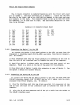
3.2
Serial
ports
The
heart
of
the
serial
I/O
ports
is
the
8251
USART
consisting
of
irrlependent
receiver
and
transmitter.
The
function
of
the
transmitter
is
to
accept
eight
bits
of
parallel
data
fran
the
data
bus,
and
convert
this
to
serial
data
with
a wide range
of
formats,
parity
and
stop
bits.
The speed
at
whim
data
is
output
in
asynchronous
mode
is
controlled
by
a
selectable
clock
rate
derived
fran
the
2
MHz
systan
clock
by
counters
U8
and
Ul. '!he
clock
rate
is
nonnally
sixteen
tines
the
required
baud
rate
(though
this
can
be changed when
the
8251
is
initialized
by
software),
so
a
frequency
of
153.6
KHz
is
required
for
9600
baud.
This
gives
a frequency
division
ratio
of
13.02,
which
is
rounded
to
13,
relative
to
the
2
MHz
clock.
U7
fonns a
divide
by 13
stage,
and
the
gated
terminal
count
at
Ul4-8
can be
selected
by a
DIP
switch
for
9600
baud.
The
other
cannon baud
rates,
3-2 Rev.
I-B
6/11/80