
User`s guide


Vector
ZCB
Single
Board
canputer
L..4.5 How
to
connect
many low
sp:ed
asynchronous
acoustic
couplers
and
IOOdems
This
section
is
applicable
to
many
acoustic
couplers
and
IOOdems
which
carry
out
asynchronous
canmunications
at
rates
of
1200 baud
or
less.
It
is
almost
always
applicable
for
asynchronous
couplers
and
modems
operating
at
300 baud
or
less.
Specifically,
it
is
applicable
to
nodems
and
couplers
which
require
only
three
RS-232C
lines
caning
fran
the
canputer:
Transmit
Data
(line
2),
Receive
Data
(line
3),
and
Signal
Ground
(line
7).
Because
the
ZCB
board
is
wired
for
direct
connection
to
a
terminal,
you
cannot
simply
connect
the
ZCB
serial
I/O
cable
to
the
modem.
This
is
because
both
the
nodem and
the
ZCB
serial
FOrt
in
its
normal
conf
iguration
are
Data
Communications
Equipment
(DCE), and
therefore
both
expect
to
receive
data
on
line
2 and
to
transmit
data
on
line
3.
Another
problem
is
that
most
modems
and
couplers
have
female
sockets,
and
the
00-25
connector
at
the
end
of
the
ZCB
serial
I/O
cable
is
also
a female
socket.
One
solution:
create
a
three
line
cable
with
male
DB-25
connectors
at
both
ends.
Wire
line
7
straight
across,
and
cross
lines
2
and
3.
In
other
~rds,
connect
pin
2
of
one
connector
to
pin
3
of
the
other,
and
vica
versa.
Such a
cable
will
~rk
with
any
modem
or
coupler
requiring
only
three
lines.
Connect
one
end
of
the
cable
to
the
DB-25
of
the
ZCB
Serial
I/O
cable
and
the
other
end
to
the
modem
or
coupler.
We
strongly
suggest
that
you
do
not
modify
the
ZCB
board
itself
or
the
ZCB
Serial
I/O
cable,
in
order
to
cross
lines
2
and
3.
By
modifying
or
adapting
the
external
cabling
instead,
the
canputer
itself
remains
standard,
and
the
serial
FOrts
can
easily
be
used
for
connecting
to
a
terminal
or
other
kind
of
peripheral
if
ever
required.
2.4.6
Connecting
additional
RS-232C handshaking
lines
If
:you
are
using
a
terminal
which
requires
handshaking
over
and
a.l:x>ve
the
+12
VDC
supplied
on
lines
5 and
6,
or
if
:you
are
using
a
modem
or
coupler
which
requires
any
handshaking
at
all,
that
is,
requires
nore
than
a
three
line
connection
(lines
2,
3 and
7),
then
continue
reading
this
section.
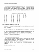
The
following
table
lists
all
25 RS-232C
lines
by
name,
number,
and
source,
and
indicates
what
subset
of
these
are
connected
to
the
ZCB
board
via
the
ZCB
Serial
I/O
cable.
For
this
subset,
the
table
specifies
each
line's
pin
number
on
the
l6-pin
socket
connected
to
the
end
of
the
ZCB
Serial
I/O
cable.
The
table
also
lists
those
lines
which
are
connected
to
COU};X)nents
or
jumper
pads,
in
the
factory
configuration
of
the
board,
and
what
they
are
connected
to.
"U16-13" m:ans
it
is
connected
to
pin
"13"
of
U16.
"GND"
indicates
the
line
is
connnected
to
Ground
in
the
factory
conf
iguration.
Rev.
l-B
6/11/80
2-15