
User`s guide

Vector
ZCB
Single
fbard
Garputer
Always
insert
the
connector
so
that
the
ribbon
cable
anerges
toward
the
.!92.
of
the
board.
You
can
double
check
this
by
checking
that
the
"1"
on
the
connector
corres{X)nds
with
the
"1"
printed
on
the
board
next
to
the
socket.
Then
install
the
OB-25
at
the
other
end
of
the
cable
into
one
of
the
available
sockets
at
the
rear
of
the
camputer,
or
wherever
convenient.
'!he
board
canes
with
one
serial
I/O
cable.
Many RS-232C
serial
terminals
and
printers,
particularly
those
\lK)rking
at
1200 baud
or
less,
require
none
of
the
RS-232C
handshaking
lines.
Some
require
that
one
of
these
handshaking
lines
be
held
at
+12
VOC.
In
either
case,
you
can
plug
these
peripherals
directly
into
the
OB-25
at
the
end
of
the
serial
I/O
cable
without
modifying
the
board
at
all
if
yoo
are
using
stnadard
Vector
Graphic
software;
because
the
software
holds
the
rrost
cannon
handshaking
lines
at
+12
VDC
-
lines
5,
6,
and
8.
rbte
that
the
ZCB
does
not
require
any hardware handshaking
signals
fran
the
peripheral
in
order
to
operate.
--
If
you
are
not
sure
whether
the
board
will
\lK)rk
without
nodification,
try
it
before
attempting
to
add
additional
handshaking
signals.
Generally,
to
make
sure
that
you
are
connecting
all
the
necessary
lines,
use
a
25-wire
ribbon
cable
between
the
OB-25
at
the
end
of
the
serial
I/O
cable
and
the
OB-25
connected
to
the
peripheral.
The
ZCB
board
does
not
generate
undesired
inhibiting
signals
on
any
of
the
lines.
001'E:
If
you
are
wr
i
ting
your
own
software,
you
will
have
to
program
the
8251
on
the
ZCB
to
control
any
handshaking
lines
required
by
the
peripheral
device.
If
it
is
simply
a
matter
of
holding
high
or
pulling
low a
line,
you
can
simply
strap
the
appropriate
pin
with
a
source
of
+12V
or
GNO
at
the
connector
before
it
even
comes
into
the
camputer.
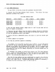
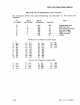
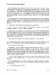
Lines
controllable
by
software
are
listed
in
the
table:
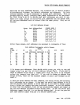
Additional
RS-232
handshaking
lines
available.
If
a
25-wire
cable
is
not
possible,
then
attempt
the
connection
using
three
wires,
connecting
RS-232C
lines
2,
3,
and
7
fran
the
08-25
at
the
end
of
the
serial
I/O
cable
to
the
same
pins
on
the
08-25
which
plugs
into
the
peripheral.
(Receive-only
printers
that
do
not
generate
acknowledgement
signals,
such
as
Teletype
or
Decwriters,
do
not
require
connecting
line
2.
It
is
never
necessary
to
connect
line
1 -
protective
ground -
because
the
ZCB
does
not
ground
it.)
If
this
does
not
work,
then
the
peripheral
may
require
one
of
the
RS-232C handshaking
lines.
The
two
most ccmron RS-232C
han:::1shaking
lines
required
by
serial
peripherals
are
Clear
to
Send (1
ine
5)
and
Data
Set
Ready
(line
6).
These
two
lines
are
held
at
+12 VDC
by
standard
software.
'!he manual
for
your
peripheral
should
specify
if
any
are
required.
To
connect
one
or
more,
simply
connect
a
wire
between
the
corresponding
desired,pin
numbers
on
the
DB-25's
at
both
ends
of
your
external
cable,
in
addition
to
the
three
lines
(2,
3,
and
7)
given
above.
Remember
that
you
do
not
have
to
worry
about
this
if
you
simply
use
a
25-wire
ribbon
cable.
2-12
Rev.
l-B
6/11/80