
User`s guide

Vector
ZCB
Single
Board Computer
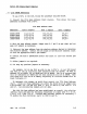
_.3.3
2716
EPROM
Addressing
To
use
2716
1
s
in
the
ZCB,
follCM
the
procedure
outlined
belcw.
1)
Consult
the
2716
Base
Address
Chart
(below).
This
shows
the
base
addresses
allowable
with
2716
1
s.
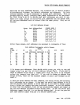
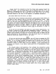
2716
Base
Address
Chart
Addresses
Area
H
JLDTq?ers
Area
I
Jumpers
Area
J
JLDTq?ers
0000H-3FFFH
1-2,2-5,3-9
8-4,7-3,6-2
3-4,6-7
4000H-7FFFH
1-2,2-4,3-9
8-4,7-3,6-2
3-4,6-7
8000H-BFFFH
1-2,2-5,3-8
8-4,7-3,6-2
3-4,6-7
COOOH-FFFFH
1-2,2-4,3-8
8-4,7-3,6-2
3-4,6-7
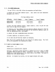
2)
With
the
base
address
chosen,
Jumper
area
H, I and J
as
per
chart
and
cut
away
old
jumpers
as
necessary.
3)
Subtract
the
base
address
fran
the
absolute
address
desired
to
determine
the
relative
address.
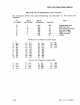
Consult
the
2K
colunn
of
the
Relative
Address
Chart
to
find
the
appropriate
Area
F
pad
number.
4)
Consult
the
Area
F
EPROM/RAM
Socket
Pad
Chart
to
find
the
second
pad
number.
5)
Solder
jLDTq?er(s)
as
required.
6)
CUt
awcry
any
previoos
jumpers
as
necessary.
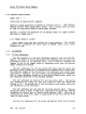
For
example,
let
us
say
that
we
wish
to
use
3-2716
1
s
on
our
ZCB
board
and
want
to
use
an
auxiliary
disk
controller
with
our
system.
We
want
to
address
U20
at
AOOOH,
U21
at
BOOOH
and
U22
at
B800H. The lK
of
on-board
RAM
will
be
addressed
at
9800H
and
the
disk
controller
will
be
at
8800H.
Note
that
there
will
only
be
lK
of
memory
beginning
at
location
9800H
with
lK
blank
following
it.
To
implement
this
dlange,
we
VtOuld
first
consult
the
2716
Base
Address
Chart.
Since
all
these
addresses
lie
within
the
third
block
we
jLDTq?er
area
H
as
follCM5:
1-2,
2-5
and
3-8;
area
I :
8-4,
7-3
and
6-2;
and
area
J:
3-4
and
6-7.
All
pre-existing
jumpers
are
cut
away.
Now
that
the
base
address
has
been
established,
we
consult
the
relative
address
chart
and make
the
following
connections
in
jumper
area
F:
1
to
10,
6
to
8,
2
to
7
and
3
to
11.
(Cutting
CMay
previoos
jumpers
as
necessary.)
To
enable
the
disk
controller,
pad
4
is
tied
to
pad
13.
Rev.
I-B
6/11/80
2-5