
User`s guide

Vector
ZCB
Single
Board
canputer
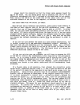
Area
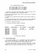
F
EPRCM/RAM
Socket
Pad
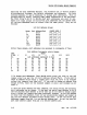
Chart
Pad 1
connects
EPRCM
0 (U20)
to
its
address.
Pad 6
connects
EPRCM
1 (U2l)
to
its
address.
Pad 2
connects
EPRCM
2 (U22)
to
its
address.
Pad 3
connects
RAM
(U24,25)
to
its
address.
If
you
want
to
use
2708's
and
change
memory
locations
outside
of
the
standard
block
(EOOOH-FFFFH)
use
the
following
procedure.
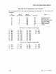
1)
Determine
which
8K
memory
block
you
want
to
use
from
the
2708
Base
Address
Chart
below.
2)
Rejumper
Area
H
as
specified
and
cut
away
any
pre-existing
jumpers
as
necessary.
3)
Use
the
Relative
Address
Chart
(aOOve)
to
determine
the
actual
EPRCM/RAM
pad
assigT'llents
within
Jumper
Area
F
as
described
in
the
last
section.
4)
Solder
Area
F
jumpers
as
required
5)
Olt
away
any
pre-existing
jumpers
as
necessary.
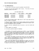
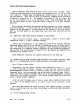
Addresses
OOOOH-lFFFH
2000H-3FFFH
4000H-5FFFH
6000H-7FFFH
8000H-9FFFH
AOOOH-BFFFH
COOOH-DFFFH
EOOOH-FFFFH
2708 Base
Address
Chart
Area H Jt.nnpers
1-7,2-5,3-9
1-6,2-5,3-9
1-7,2-4,3-9
1-6,2-4,3-9
1-7,2-5,3-8
1-6,2-5,3-8
1-7,2-4,3-8
1-6,2-4,3-8*
Area
I
Jumpers
N:l
change
Std:
3-6,4-7,5-8
*
Standard
Area
H
Jumpering
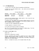
2.3.2
Auxiliary
Memory
Disable
Area
J
Jumpers
N:l
change
Std:
2-4,5-7
If
you
want
to
disable
1
or
2
l-K
increments
of
main merrory
(perhaps
to
use
an
auxiliary
disk
controller
or
video
board.)
jumper
pad
4
and/or
5
of
jumper
area
F
to
the
pad
representing
the
absolute
address
desired.
This
memory
disable
feature
will
work
with
whatever
EPRCM
type
is
chosen
except
that
the
interval
disabled
will
be
2K
if
the
board
has
been
configured
for
2716's
and
4K
if
the
board
has
been
set
up
for
2732's.
2-4
Rev.
l-B
6/11/80