
User`s guide


Vector
ZCB
Single
Board
Canputer
II.
USER'S
GUIDE
2.1
Introduction
The
User's
Guide
explains
how
the
board
functions
as
manufactured
and
tells
how
to
change
various
user
selectable
q>tions
by
neans
of
jumpers
and
switches
to
fit
other
than
standard
requirements.
The
User's
Guide
is
divided
into
3
sections
to
cover
the
three
main
areas
of
board
operation:
CPU
section,
EPRCM/RAM
section
and
I/O
section.
2.1.1
Standard
jumpering
and
what
it
does
The
Vector
Graphic
ZCB
single
roard
canputer
has
been
prejumpered
at
the
factory
to
fit
current
Vector
Graphic
Microcanputer
Systems.
If
you
wish
to
use
the
ZCB
in
another
model
computer
or
one
of
your
own
design,
the
following
infonnation
will
prove
useful.
The
standard
jumpering
does
the
following:
2.2
CPU
SECrIGl
2708
EPROM's
are
selected
for
2
PROM
sockets.
2716
EPROM
selected
for
1
PROM
socket.
EPROM
base
address
is
EOOO.
lK
on-board
menory
is
addressed
at
FCOO.
Serial
p::>r.t
is
addressed
at
04(control)
and
05(data)
(Same
information
is
duplicated
at
addresses
06 and 07)
Parallel
p::>rts A,B,C and
Control
Status
Register
are
addressed
at
08,09,OA and
OB,
respectively.
Clock
speed,
4MHz.
Mwri
te
is
enabled
One
wait
state
is
inserted
on
each
Ml
cycle.
On-board
EPROM
is
enabled
to
boot
on
reset.
Phantan
(line
67)
is
enabled.
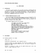
2.2.1
Running
system
at
2
or
4
MHz.
Jumper
area
A
Connections
as
manufactured:
pad
1 jumpered
to
pad 2
Function:
selects
2
or
4
MHz.
q:>eration.
The Z-80
CPU
is
capable
of
4
MHz.
operation
but
same
peripheral
boards
are
not.
The
board
is
shipped
for
operation
at
4
Mhz.
Options:
to
operate
at
2
MHZ,
cut
the
jumper
between
pad
1
and
2
and
install
a jumper
be~n
pad 1 and
3.
Rev.
l-B
6/11/80
2-1