
User's Guide

12 APCD-LM011-A
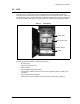
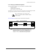
2 Installing the NAP and the CAP
2.2 Setting up the NAP Using the Default Configuration
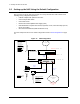
After you have set up the CAP, the next step is to set up the NAP. The NAP consists of the
following factory configured components:
• Cabinet complete with power bar and fans
• Cisco Catalyst 2924 Switch
• Cisco 2621 Router
• Exide 5119 Uninterruptible Power Supply (UPS)
• NMS Workstation complete with monitor, keyboard, mouse, internal backup tape unit,
printer, and cables
• APC Back-UPS PRO 650 (NMS Workstation UPS)
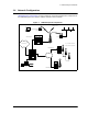
The NAP components all use the default configuration shown in
NAP Configuration
on page
12.
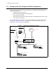
Figure 10 NAP Configuration
Cisco Catalyst 2924 Switch
Cisco 2621 Router
Interface 0/0
10.2.23.1 /24
Interface 0/1
192.168.10.1 /24
Port 1
192.168.10.5 /24
NMS Server
Straight
Cable
Straight
Cable
Port 2 Port 24
192.168.10.7 /24
Port 3
192.168.10.6 /24
Straight
Cable
CAP BackHaul
Circuit
To Internet
NAP UPS
Cross-Over
Cable
Connect to Port Ax
on CAP Ethernet
Switch
SNMP Communities:
read: public
write: private
trap: private
Trap Server IP:
192.168.10.7
UserName:
cisco
Password
: cisco
Enable Secret
Password:
cisco
UserName:
Admin
Password
:
(blank)
SNMP Communities:
read: public
write: private
trap: private
Trap Server IP:
192.168.10.7