
User's Guide
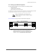

2 Installing the NAP and the CAP
8 APCD-LM011-A
2.1 Setting up the CAP Using the Default Configuration
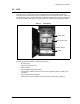
The CAP is the first component that you should set up. It consists of the following factory
configured components:
• Cabinet with power bar and fans
• Exide 5119 Uninterruptible Power Supply (UPS)
• Cisco Catalyst 1912 Switch
• CAP Channel Units (CCUs) complete with cables, bulkhead lightning arrestor, power
cords, antennas, and cables
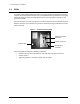
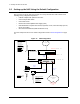
The CAP configuration can include 1 to 3 CCUs, depending on your requirements. Refer to
CAP Default Configuration (CAP #1)
on page 8 for the default configuration for the CAP
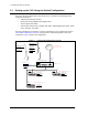
components. Figure 6 shows CCU configuration.
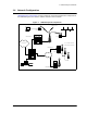
Figure 6 CAP Default Configuration (CAP #1)
Cisco Catalyst 1912 Switch
192.168.10.10 /24
Cross-Over
Cable
CCU #1
Port Ax
CCU #2
Ethernet:
192.168.10.14 /24
Ethernet:
192.168.10.13 /24
Radio:
192.168.111.1
Radio:
192.168.110.1
Straight Cable
Port 3
Port 1
192.168.10.11 /24
Straight
Cable
CAP UPS
Ethernet
BackHaul to NAP
Connect to Port of
NAP Ethernet Switch
CCU #3
Ethernet:
192.168.10.15 /24
Radio:
192.168.112.1
Port 2
Port 4
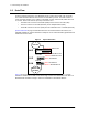
SNMP Communities:
Read: Public
Write: Private
Trap: Private
Trap Server IP:
192.168.10.7
Write Manager:
192.168.10.7
Password
: Cisco
SNMP Communities:
Read: Public
Write: Private
Trap: Private
Trap Server IP:
192.168.10.7
Local ID:
1010
Radio Channel
: 3
Local ID:
1011
Radio Channel
: 6
Local ID:
1012
Radio Channel
: 9