
User's Guide

6 APCD-LM011-A
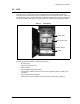
1 Understanding the LMS3200
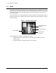
1.5 Data Flow
From the simplest perspective, the LMS3200 system consists of the NAP, CAP, and EUM.
The communications between these devices is controlled by routers. The NAP contains a
router, the CAP contains a CCU, which is essentially a router, and the EUM, which also acts
as a router. Each router has two (or more) connections on it.
• The NAP router connects to the WISP (WAN) and the CCU in the CAP (LAN).
• The CCU connects to the NAP (Ethernet) and to multiple EUMs (radio).
• The EUM connects to the CCU (radio) and the subscriber’s PC or network (Ethernet).
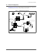
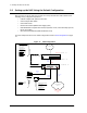
System Data Flow
on page 6 further illustrates the connections between the Internet, the
LMS3200 equipment, and the subscriber’s computer or LAN. It also identifies typical default IP
addresses for each router.
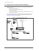
Figure 5 System Data Flow
Figure 5 shows the default IP addresses for the NAP router, CCU, and EUM. The WAN
interface IP address for the NAP router will change to reflect the subnetwork of the ISP. The
EUM Ethernet IP wll also change to reflect the subscriber’s subnetwork address.
Internet
Subscriber
Network
Interface 0/0
10.2.23.1 /24
Interface 0/1
192.168.10.1 /24
NAP
CCU-1010
Ethernet:
192.168.10.13 /24
Radio:
192.168.110.1
CAP
Ethernet:
192.168.210.2 /24
EUM-101
Radio:
192.168.110.2
EUM