
Installation and Operation Manual


NCL1100 Installation & Operation Manual
1990/07/21 – 3 –
Contents
1 INTRODUCTION ....................................................................................................................................4
1-1 Parts List...........................................................................................................................................4
1-2 About the NCL1100 Network Communications Link ........................................................................4
2 INSTALLATION.......................................................................................................................................5
2-1 Preparation .......................................................................................................................................5
2-2 NCL1100 Installation ........................................................................................................................5
2-3 LAN Connection................................................................................................................................7
2-4 Normal Operating Messages............................................................................................................7
2-5 Error Messages ................................................................................................................................8
3 DIAGNOSTICS .......................................................................................................................................8
4 SNMP INSTALLATION .........................................................................................................................12
List of Tables
Table 1: pcagent.cfg Fields and Default Values.........................................................................................12
List of Figures
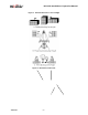
Figure 1: Potential Obstacles to Line-of-Sight ..............................................................................................6
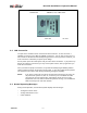
Figure 2: Back Panel, Indoor Unit.................................................................................................................6
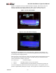
Figure 3: Screen, Normal Mode ...................................................................................................................9
Figure 4: Screen, RF Packets Outgoing.......................................................................................................9
Figure 5: Display for Local RF Site during Testing .....................................................................................10
Figure 6: Display for Remote RF Site during Testing.................................................................................10
Figure 7: Display for Local and Remote Sites During Testing....................................................................11
Figure 8: Spectrum Analyzer Display of Interference .................................................................................11
Table of Revisions
Revision Date Comments
July 21, 1999 Preliminary user manual release