
Installation and Operation Manual


NCL1100 Installation & Operation Manual
1990/07/21 – 9 –
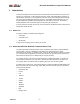
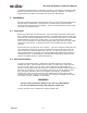
Figure 4: Screen, RF Packets Outgoing
As well as the normal display screen, the NCL1100 has a diagnostic utility included. This
utility diagnoses the RF link; use it only if the NCL1100 display shows that the RF link failed
(no incoming and/or outgoing packets).
After you run the
tt and yy RF tests, connect the LAN and attempt communication across the
link. By leaving the LAN disconnected until you run all RF tests, you can determine which
side of the link has the problem, LAN or RF.
Press these keys: to have this happen:
T T <Enter> 1496-byte packets are sent in one direction
Y Y <Enter> 1496 byte packets go in both directions and activate the remote unit
The screen displays the packets sent and received by the system. These packets are test
packets of approximately 1496 bytes in length. The bar graphs on the lower half of the screen
show the packets received and sent since the last screen update. The system updates the
screen approximately once/second. Outgoing packets are shown even if the RF link, between
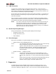
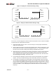
the local and remote RF sites, is not working. If the RF link is not working, however, no
incoming RF packets are shown at the remote RF site even if the local RF site is placed in a
test mode so that the local site generates outgoing RF packets. If only one end is transmitting
and the other end is receiving, then the RF utilization shows 84% incoming at the remote site
and 84% outgoing at the local site, unless interference or another system decreases
performance. Refer to Figure 5 and Figure 6. To terminate this test, power off and then on
both indoor units, or press
T or Y once.