
Installation and Operation Manual


NCL1100 Installation & Operation Manual
1990/07/21 – 5 –
The NCL1100 unit determines its environment at power-up, and builds its own address tables
based on the observed activity on the LAN segment to which it is attached. The system is
designed this way to minimize the required set-up and user administration.
2 Installation
Although the NCL1100 Network Communications Link is as user-friendly as possible, keep in
mind the design considerations. The NLC1100 is a complete point-to-point microwave
system that uses spread-spectrum techniques. Take the same precautions as you do when
you install any microwave system.
2-1 Preparation
Evaluate the path length and characteristics. Unless the path fits the default characteristics,
have a qualified engineer perform path calculations. The default characteristics include using
50 feet (16.7 m) of coaxial cable between the antenna and the indoor system. The maximum
distance between the antennae is 5 miles (8 km). You can make trade-offs with these
factors, such as extending the cable length by having a higher-gain antenna or having a path
shorter than 5 miles (8 km). As distance increases, you must maintain proper obstacle
clearance.
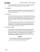
Ensure that the line-of-sight exists; refer to Figure 1. You have a clear line-of-sight when you
can clearly see the remote site, as well as the required Fresnel zone clearance, when you
stand on the first site and look towards the second site. As well, ensure that there are no
large reflective surfaces on the path, such as large buildings with metallic glass surfaces or
crowded parking lots. Avoid installation on tall downtown buildings where higher-powered
systems are installed, because of potential interference.
2-2 NCL1100 Installation
You must install the indoor unit in a temperature-controlled environment, and provide a
110/230 VAC outlet. The unit draws less than 5 amps. The indoor unit is stand-alone and
can sit on a shelf or desk, or you can mount it on the wall with the optional wall-mount
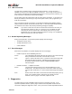
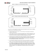
brackets. Do not power up the units until they are connected to the LAN and RF interfaces at
both sites; refer to Figure 2. This is necessary to ensure that the start-up diagnostic tests
pass, and proper terminations prevent the equipment from damage. As well as the
110/230 VAC, 50/60 Hz connection and a coaxial cable from the antenna, make a third
connection to the indoor unit from the LAN itself. This connection is available in three types
on the back of the unit: 10BASE-T, AUI, and BNC.
WARNING!
You may cause permanent damage to the unit if any NCL1100 RF
port is not terminated correctly and you power up the unit.
Connect the indoor unit to a 110/230 VAC, 50/60 Hz power outlet.