
Installation and Operation Manual


NCL1100 Installation & Operation Manual
1990/07/21 – 10 –
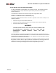
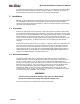
Figure 5: Display for Local RF Site during Testing
Incoming
Outgoing
Filtered
Incoming
Outgoing
Percent
Utilization
Overload
LAN RF
11 Mb/s
10 Mb/s
020406080100
0 20 40 60 80 100
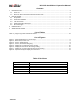
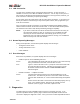
Figure 6: Display for Remote RF Site during Testing
Incoming
Outgoing
Filtered
Incoming
Outgoing
Percent
Utilization
Overload
LAN RF
11 Mb/s
10 Mb/s
020406080100
020406080100
You can use a second diagnostic method to test the RF link, but it does not test the hardware.
To perform this test, follow these instructions:
1. Power both indoor units off, then on, to ensure that you use the proper command line
during the test procedure.
2. After the NCL1100 system is running and the display screen appears at both sites, at the
local site press the
R key to activate the display, then press yy. This action places both
RF sites in the test mode, sending and receiving the opposite site’s packets.
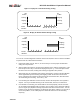
3. When both sites are transmitting and receiving test packets, check that the RF utilization
shows approximately 44% incoming and outgoing at both the local and remote sites.
Figure 7 illustrates the monitors for both the remote and local RF sites, when both sites
are transmitting and receiving. This is the
yy test.
4. If the incoming RF utilization is less than 44%, then the RF link portion of the system is
suspect. Focus your trouble-shooting on the coaxial cable, antenna, or interference.
5. If the RF link is not working, the coaxial cable is connected properly, and the antennae
are in unobstructed alignment with each other, then you many need a spectrum analyzer
(refer to Figure 8) to pinpoint interfering frequencies and take corrective action. You can,
however, move the antenna slightly in an alignment-type pattern, while it is on its mast, to
correct the problem; or use nearby objects to shield the antenna from the offending
frequency.