
User Manual
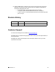
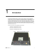
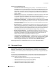
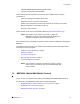
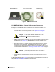
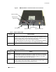
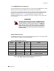
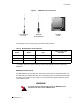
Table Of Contents

1: Introduction
APCD-WM001-1.0 5
Figure 2 MMT9000 Components
1.3.1 MMT9000 Modem - External Indicators and Connectors
All interfaces on the MMT9000 are on one side of the radio for ease of installation. The
following interfaces are:
• Ethernet port - 10BaseT RJ45 receptacle to connect the modem to the end-user’s
computer. Details on the Ethernet port are found in Appendix B on page 29.
CAUTION: Any DC voltage applied to the Ethernet port may
damage the MMT9000, the Ethernet cable, and/or network gear.
The MMT9000 is not
a Power-over-Ethernet device.
• SMA-F Antenna Port - for connecting one of the approved mobile or fixed antennas to
the MMT9000. See section 1.3.2, MMT9000 Suite of Antennas for details on the
antennas.
• DC Power Connector - a watertight, locking 4 pin receptacle receives the connector
from vehicle power system cable. The MMT9000 comes with an 18-ft. cable for
connecting to the vehicle power system as well as a fuse assembly. The pin out and
connection details are discussed in Connecting to Vehicle Power System on page 14.
CAUTION: Use standard vehicle power system (13.8 VDC +/-
25%) only. Any other voltage can result in damage to the modem.
• Chassis Ground Lug - this should be connected to the vehicle chassis or ground
system.
The MMT9000 also has 3 LEDs. Figure 3 shows the layout of the MMT9000 Connectors and
LEDs, while Table 1 and Table 2 explain what each LED means.
MMT9000 Modem
Fuse Assembly12 VDC Power Cable